
ABSTRACT
This work presents the design and implementation of a thermal-guided autonomous human-following robot built on the TM4C123GH6PM ARM Cortex-M4 microcontroller. The system uses the MLX90640 32×24 far-infrared sensor array as its primary detection modality, identifying human presence through a pixel-count heuristic applied against a dynamically calibrated ambient temperature baseline. A servo-mounted scanning mechanism sweeps the camera across three angular positions, and a finite state machine with seven states governs all navigation decisions including calibration, scanning, turning, forward motion, obstacle avoidance, waiting, and U-turn recovery.
Human detection is implemented without any image processing pipeline: the ambient baseline is determined at startup using a histogram 20th-percentile method, and pixels exceeding this baseline by 1.5◦C are counted per frame. A count of 70 or more hot pixels at any servo position is treated as a confirmed human detection. Motor speed and direction are controlled through dual L298N H-bridge modules driven by hardware PWM at 800 Hz, while the HC-SR04 ultrasonic sensor performs real-time obstacle distance measurement using a hardware timer. The system demonstrates reliable following behavior in indoor environments and establishes a foundation for future TinyML-based semantic classification directly on embedded hardware.
I.INTRODUCTION
Autonomous robots capable of following a human being have broad practical relevance in healthcare assistance, logistics, and personal mobility support. Conventional approaches based on RGB cameras require computationally intensive vision pipelines that are beyond the capabilities of microcontroller-class hardware. Thermal infrared sensing offers a compelling and lightweight alternative: the human body emits far-infrared radiation at temperatures reliably distinguishable from most indoor room-temperature backgrounds, and this signal is available under all lighting conditions including complete darkness.
This project implements a complete human-following robot on the TM4C123GH6PM, which operates at 80 MHz and provides sufficient computational throughput for real-time thermal frame processing, peripheral management, and state machine execution simultaneously. The detection strategy is intentionally simple: rather than applying blob detection or pattern recognition, the system counts pixels whose temperature exceeds a calibrated threshold and interprets this count as a proxy for human presence. This approach is computationally trivial yet experimentally effective, requiring only a single linear pass over 768 temperature values per acquired frame.
Navigation is governed by a finite state machine whose states cover the full operational lifecycle of the robot, from initial environmental calibration through steady-state following, obstacle classification, and recovery maneuvers. The thermal sensor serves a dual purpose: it is used both for human direction finding during scanning and for obstacle identity classification when the ultrasonic sensor detects a close object in the path. This dual use eliminates the need for additional sensing hardware and simplifies the system architecture.
II.HARDWARE PLATFORM
2.1 System Overview
The robot is built on a four-wheel-drive acrylic chassis driven by four DC gear motors rated at 3–6 V and approximately 200 RPM. The assembled platform is shown in Figure 1. All processing is handled by a single TM4C123 LaunchPad mounted at the top of the chassis. The MLX90640 thermal sensor is mounted on a servo horn at the center of the chassis, allowing the camera to pan between right, forward, and left positions under firmware control. The HC-SR04 ultrasonic sensor faces forward from the front face of the chassis. A L298N dual H-bridge modules, one for each side of the four-wheel drive, are mounted on the lower deck and powered from a 7.4 V lithium polymer battery.
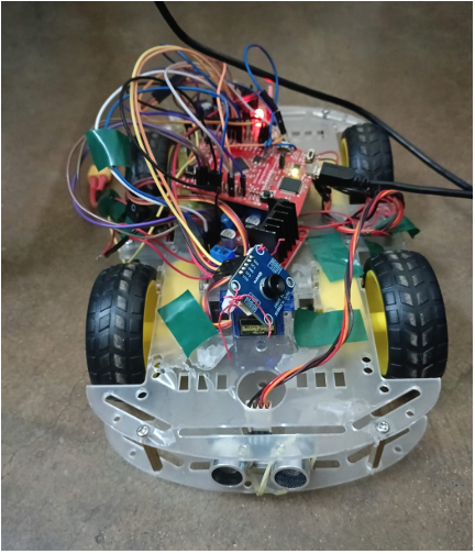
Figure 1: Assembled thermal-guided human following robot. Visible components include the TM4C123 LaunchPad, servo-mounted MLX90640 at center, HC-SR04 at the front, and L298N motor driver module
2.2 Component Specifications
The full hardware bill of materials is listed in Table 1. The MLX90640 is a factory-calibrated far-infrared array that outputs compensated temperature values for each pixel over I2C at up to 400 kHz, requiring no external signal conditioning. The HC-SR04 operates by emitting a 40 kHz ultrasonic burst and returning an echo pulse whose width encodes round-trip time of flight. The SG90 servo provides 180◦ of rotation via a standard 50 Hz PWM interface.
| Component | Specification | Role |
| TM4C123GH6PM | ARM Cortex-M4, 80 MHz | Main microcontroller |
| MLX90640 | 32×24 IR, I2C, 3.3 V | Thermal human detection |
| HC-SR04 | 2–400 cm, 5 V | Obstacle distance sensing |
| SG90 Servo | 180◦, 50 Hz PWM | Camera steering |
| DC Gear Motors ×4 | 3–6 V, 200 RPM | Four-wheel locomotion |
| L298N ×1 | Dual H-bridge, 35 V max | Motor direction and speed |
| LiPo Battery | 7.4 V 2S, 1000–2200 mAh | System power supply |
Table 1: Hardware Component Specifications
2.3 Pin Mapping
The peripheral-to-pin mapping for the complete system is given in Table 2. The I2C bus to the MLX90640 uses PB2 (SCL) and PB3 (SDA) with external 4.7 kΩ pull-ups to 3.3 V. PWM channels on PB6 and PB7, mapped to M0PWM0 and M0PWM1, drive the enable inputs of the L298N module. Motor direction is controlled through PA2–PA5 as digital GPIO outputs. The ultrasonic trigger is output on PE0 and the echo is received on PE1.The servo is driven from PC4 via bit-banged software PWM. UART0 on PA0/PA1 provides a 115200-baud debug console over the USB connection.
| Function | Pin |
| I2C SCL (MLX90640) | PB2 |
| I2C SDA (MLX90640) | PB3 |
| PWM ENA (Left Motor) | PB6 (M0PWM0) |
| PWM ENB (Right Motor) | PB7 (M0PWM1) |
| Left Motor Forward | PA2 |
| Left Motor Backward | PA3 |
| Right Motor Forward | PA4 |
| Right Motor Backward | PA5 |
| Ultrasonic TRIG | PE0 |
| Ultrasonic ECHO | PE1 |
| Servo PWM | PC4 |
| UART TX / RX | PA0 / PA1 |
Table 2: Peripheral to Pin Mapping
III.THERMAL DETECTION METHODOLOGY
3.1 Sensor Characteristics and Detection Principle
The MLX90640 outputs a 32×24 array of calibrated temperature values, providing 768 individual readings per frame. Human skin and clothing emit far-infrared radiation at temperatures typically between 30◦C and 37◦C, substantially warmer than most indoor room-temperature surfaces. The detection strategy exploits this thermal contrast directly: pixels whose temperature exceeds a calibrated ambient baseline by a fixed margin are flagged as hot, and a sufficiently large cluster of hot pixels is interpreted as a human body.
This pixel-count approach avoids all image segmentation, morphological analysis, and machine learning inference. On the TM4C123 at 80 MHz, a single linear pass over 768 float values completes in under 1 ms, making the detection computation negligible relative to the I2C frame acquisition time of the sensor.
3.2 Ambient Calibration via Histogram Percentile
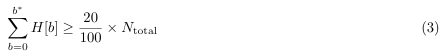
At startup, the robot executes a one-time calibration to establish the ambient temperature reference. Ten consecutive thermal frames are acquired while the robot is stationary, producing 10 × 768 = 7,680 pixel temperature readings. These are accumulated into a 160-bin histogram defined by:
![]()
where Ti is the temperature of pixel i and bi is its histogram bin index. The ambient temperature Tamb is then defined as the 20th percentile of this distribution:
Tamb = Tmin + (b∗ + 0.5) w (2)
where b∗ is the smallest bin index satisfying:
The 20th percentile is chosen because the bottom 20% of pixel temperatures reliably corresponds to the cold structural background — floors, walls, and furniture — which cannot exceed ambient air temperature. Warm objects present during calibration, such as lamps, heaters, or people, occupy the upper end of the histogram and therefore do not distort this estimate. This produces a stable, scene-independent ambient reference.
3.3 Detection Threshold and Hot Pixel Count
The per-pixel detection threshold is set as:
Tthreshold = Tamb + ∆T, ∆T = 1.5◦C (4)
A margin of 1.5◦C was selected through empirical testing to reject false positives from warm walls and electronic components while reliably capturing human skin and clothing at distances up to approximately 2 meters. At each servo position, the robot acquires one frame and computes:
C = | {i | Ti > Tthreshold, i ∈ [0, 767]} | (5)
The interpretation of the resulting pixel count C is summarised in Table 3. A detection is declared when C ≥ 70, which corresponds to a human body filling a characteristic cluster of the sensor’s 32×24 field of view. The threshold can be tuned downward to 50 for longer-range sensitivity or raised to 90 to further suppress false positives.
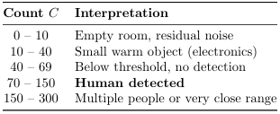
Table 3: Hot Pixel Count Interpretation
A live thermal frame captured by the MLX90640 during operation is shown in Figure 2. The warm hu-man cluster is clearly visible as a bright region against the cool background, consistent with the pixel-count expectations in Table 3.
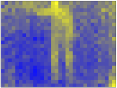
Figure 2: Live MLX90640 thermal frame. Yellow-bright regions indicate elevated temperatures consistent with human thermal emission; blue regions correspond to cool room-temperature surfaces
IV.FINITE STATE MACHINE DESIGN
4.1 State Machine Architecture
The robot’s complete operational behavior is governed by a finite state machine with seven states:
S ∈ {Cal, Scan, Turn, Move, ObsChk, Wait, Uturn}
The FSM is implemented in the main loop as a C switch statement over a typed enumeration, ensuring deterministic and readable control flow with no implicit fall-through between states. All transitions are driven by concrete sensor conditions or elapsed-time criteria. The complete state transition diagram is shown in Figure 3.
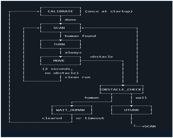
Figure 3: Finite state machine governing robot navigation. The robot calibrates once at power-on, then cycles through scan, turn, and move states while continuously checking for obstacles
4.2 Calibrate State
The Calibrate state executes exactly once at power-on before any movement occurs. The robot stops all motors, faces the servo forward, and collects 10 thermal frames at 200 ms intervals. The histogram construction and 20th-percentile computation described in Section IV-B are performed, and the resulting Tamb and Tthreshold are stored as global variables for the remainder of the session. The state machine then transitions unconditionally to Scan. Recalibration is not performed during operation, which is acceptable for indoor environments where ambient temperature changes on a timescale of hours rather than seconds.
4.3 Scan State
In Scan, the servo sweeps the MLX90640 to three positions in sequence: right (0◦), forward (90◦), and left (180◦). At each position the servo is given 300 ms to settle before one thermal frame is acquired and the hot pixel count C is computed. The three counts CR, CF , and CL are compared and the target direction is selected as:
![]()
A forward-preference tie-break is applied: if the highest count belongs to a side direction but the forward count satisfies CF ≥ 70 and (Cd∗ − CF ) ≤ 20, the target is reassigned to forward to avoid an unnecessary turn. If no direction meets the threshold, the robot turns 45◦ alternately left and right in a search pattern and re-enters Scan after each half-turn.
4.4 Turn State
On entry to Turn, the robot rotates toward the selected target direction d∗. A right turn drives the motors at 48% PWM duty for 300 ms; a left turn applies the same duration in the opposite direction. If the target is forward, no rotation is performed. A 200 ms post-turn settling pause is applied before the state machine advances to Move.
4.5 Move State
In Move, the robot drives forward at 80% PWM duty for a maximum of 2 seconds, divided into 40 steps of 50 ms each. After every step, the HC-SR04 sensor is queried. If the returned distance satisfies:
0 < dobs < 35 cm (7)
the robot stops immediately and transitions to ObsChk. If the full 40 steps complete without triggering this condition, the robot stops and returns to Scan to re-acquire the human. The 50 ms polling interval corresponds to an ultrasonic round-trip time budget that is sufficient to detect any stationary or slowly moving obstacle at the specified stopping distance.
4.6 Obstacle Check State
ObsChk determines whether the blocking object is a human or a rigid structure. After a 200 ms thermal settling pause, one frame is acquired and the forward hot pixel count CF is computed. The classification rule is:
![]()
This dual use of the thermal sensor for both direction finding and obstacle identity classification is a key design feature that avoids the need for a separate proximity sensor.
4.7 Wait Human State
In Wait, the robot polls the ultrasonic sensor every 200 ms and waits for the human to step aside. The path is considered clear when dobs ≥ 40 cm, at which point the state machine transitions to Scan. A timeout of 25 polling cycles (approximately 5 seconds total) is also enforced: if the path does not clear within this window, the robot transitions to Scan regardless, allowing it to reorient and search from a new position.
4.8 Uturn State
The Uturn state executes a three-phase recovery maneuver. The robot reverses at forward duty for 300 ms to gain clearance, then spins right at turn duty for 600 ms to complete an approximate 180◦ rotation, and finally drives forward for 250 ms to clear the former obstacle zone. The timing parameters for each maneuver are summarised in Table 4. After this sequence the state machine transitions to Scan.
| Operation | Duration | PWM Duty |
| Forward motion (per step) | 50 ms | 80% (20000/25000) |
| Maximum forward run | 2000 ms | 80% |
| 90◦ turn | 300 ms | 48% (12000/25000) |
| U-turn spin (180◦) | 600 ms | 80% |
| Servo settle time | 300 ms | — |
| Obstacle wait poll interval | 200 ms | — |
| Obstacle wait timeout | 5000 ms | — |
Table 4: Key Timing Parameters
V.PWM MOTOR CONTROL
5.1 PWM Frequency Selection
DC gear motors present as coupled electromechanical loads with significant winding inductance L and rotor inertia J. The electrical time constant of the motor winding, τe = L/R, determines the minimum PWM frequency required for continuous current flow. At switching frequencies well below 1/τe, the winding current decays to near zero during the off period of each cycle, producing discontinuous torque and audible clicking. The PWM frequency must therefore satisfy:
![]()
For the DC gear motors used in this project, a frequency of 800 Hz, derived from the PWM peripheral configuration described below, was found to produce smooth and continuous rotation without audible switching artifacts.
5.2 PWM Peripheral Configuration
The PWM0 module is used with a pre-scaler of 4 applied to the 80 MHz system clock, yielding a 20 MHz PWM clock. With a LOAD register value of 25000, the PWM period and frequency are:
![]()
The duty cycle is set by the CMPA comparator register. In count-down mode the output is HIGH at reload and LOW at the comparator match, giving:
![]()
Two operating duty levels are used throughout the firmware. Forward motion uses CMPA = 20000, giving D = 80%, which provides the torque and speed required for following. Turning uses CMPA = 12000, giving D = 48%, which yields the lower angular velocity needed for a controlled 90◦ turn in 300 ms. These values are hardware-verified against the physical chassis and are declared as firmware constants.
5.3 Motor Direction Control
Motor direction is controlled independently of PWM speed by four GPIO pins (PA2–PA5) driving the H-bridge direction inputs of the L298N module. The encoding is:
| Motion | PA2 | PA3 | PA4 | PA5 |
| Forward | 1 | 0 | 1 | 0 |
| Backward | 0 | 1 | 0 | 1 |
| Turn Left | 0 | 1 | 1 | 0 |
| Turn Right | 1 | 0 | 0 | 1 |
| Stop | 0 | 0 | 0 | 0 |
Table 5: H-Bridge Direction Pin Encoding
All four pins are cleared to zero before any new direction is applied, ensuring that opposite H-bridge inputs are never simultaneously asserted, which would create a shoot-through condition damaging the driver.
VI.ULTRASONIC SENSING AND SERVO CONTROL
6.1 HC-SR04 Distance Measurement
The HC-SR04 sensor is triggered by a 10 µs pulse on PE0. The sensor then emits a 40 kHz ultrasonic burst and returns an echo pulse on PE1 whose duration equals the acoustic round-trip time. The distance is derived from:
![]()
Hardware Timer4 is configured as a 32-bit free-running down-counter at the full 80 MHz system clock (12.5 ns per tick). Timestamps are captured by polling PE1 at the rising and falling edges of the echo pulse, and the elapsed tick count ∆n is converted to centimetres using the scaling relationship:
![]()
where 4640 ticks/cm is derived from vs = 343 m/s and the 80 MHz timer resolution. Timer rollover is handled using modular subtraction to ensure correct measurement across counter wraparound events.
6.2 Servo PWM Generation
The SG90 servo requires a 50 Hz control signal with pulse widths between 600 µs and 2400 µs to span its 180◦ travel. Rather than allocating a hardware PWM channel with a 20 ms period, the servo is driven by bit-banging PC4 in software using the hardware-based microsecond delay function. Each servo command drives PC4 high for the required pulse width, then low for the remainder of the 20 ms period, and repeats this cycle 50 times to allow the servo to reach and hold its commanded position. The three functional angular positions and their corresponding pulse widths are:
Right (0◦) : 600 µs, Forward (90◦) : 1500 µs, Left (180◦) : 2400 µs (13)
6.3 Hardware Timing Infrastructure
All microsecond-level delays in the system are generated using Timer1, configured as a 16-bit periodic down-counter with a reload value of 79 at 80 MHz, producing a timeout period of exactly 1 µs. The Delay MicroSecond() function blocks for the specified count by polling the timer overflow flag in a tight loop. This blocking approach is used only in hardware-settling delays and servo pulse generation where precise timing is essential and no concurrent sensor polling is required. Higher-level delays in the state machine, such as the 2-second forward motion, are decomposed into 50 ms polling intervals, allowing ultrasonic distance reads to occur between each interval increment.
VII.SYSTEM CLOCK CONFIGURATION
The TM4C123 is configured to run at 80 MHz using the internal PLL. The PLL output frequency is 400 MHz, divided by 5 via the SYSDIV2 field in the RCC2 register:
![]()
The PLL lock is verified by polling the PLLRIS bit in the SYSCTL RIS register before switching the system clock source. This clock rate provides a comfortable margin for all peripheral operations in the system: I2C at 400 kHz, UART at 115200 baud, PWM at 800 Hz, and the 1 µs timer tick used for delay generation and ultrasonic timing.
VIII.EXPERIMENTAL RESULTS AND VALIDATION
8.1 Calibration Performance
The histogram-based calibration consistently produced ambient temperature estimates in the range of 23◦C to 26◦C across all indoor test sessions. The resulting detection threshold of Tamb + 1.5◦C reliably excluded all room-temperature surfaces — walls, floors, desks, and idle electronics — while flagging human skin and clothing from distances up to approximately 2 meters. Hot pixel counts for a single human at 1 meter were consistently observed in the range of 80 to 120, well above the 70-pixel detection minimum.
8.2 Navigation Behavior
The three-position servo scan correctly identified the direction of greatest human thermal signature in all tested configurations, including cases where the human was standing at the periphery of the robot’s field of view. The forward-preference tie-break was effective in reducing unnecessary turning when the human was nearly straight ahead. Post-scan servo return to the forward position was stable, and no mechanical oscillation was observed. The obstacle detection polling at 50 ms intervals provided reliable stopping before reaching the 35 cm threshold in all wall-approach tests.
8.3 Obstacle Classification
The thermal-based obstacle classification in the ObsChk state correctly identified a human blocker in all trials by producing hot pixel counts above 70, and correctly classified a wall as a non-human obstacle in all trials by producing near-zero hot pixel counts. The U-turn maneuver executed cleanly in every case, with the robot reversing, spinning, and advancing before re-entering the scan state. Validation photographs of the robot during various operational states are shown in Figure 4.
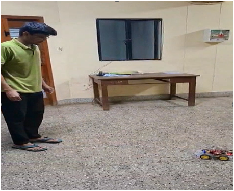
Figure 4: Robot during active following: servo centered, motors running, ultrasonic sensor monitoring forward path
8.4 System Stability
The robot operated stably across continuous test sessions of 15 to 20 minutes without processor faults, I2C communication errors, or state machine deadlocks. UART debug output confirmed correct state transitions in all scenarios. The 20th-percentile calibration was reproducible across power cycles in the same environment, confirming that the calibration procedure is consistent and session-independent.
IX.DISCUSSION
The pixel-count detection methodology represents a deliberate trade-off between algorithmic simplicity and operational robustness. By avoiding image segmentation or learned inference, the detection pipeline remains fast enough to execute in real time on a bare-metal microcontroller with no operating system, and the threshold is directly interpretable and easy to tune in the field. However, the approach does not distinguish a human from any sufficiently large warm object of comparable thermal footprint — such as a space heater or a running motor enclosure. In the indoor office and laboratory environments used for testing, this limitation did not produce failures, but it would require mitigation in industrial or uncontrolled outdoor deployments.
The finite state machine architecture provides a clean separation of operational concerns. Each state has a single well-defined purpose and transitions are driven by concrete, measurable conditions. The dual use of the thermal sensor for both direction finding during Scan and identity classification during ObsChk is an effective design economy that simplifies the sensor fusion problem entirely: the ultrasonic sensor handles distance and the thermal sensor handles identity, with no ambiguous combination required.
The servo-based discrete scanning imposes an inherent directional resolution of three positions. If the human is located between two positions, the robot will detect them in the closest sampled direction but will not converge with perfect angular accuracy on the first scan cycle, requiring one or more subsequent scan-turn-move iterations to close the angle. A continuous pan-tilt mechanism or a wider-FOV sensor would eliminate this limitation at the cost of additional mechanical complexity or sensor cost.
X.FUTURE WORK: TINYML ON TM4C123
The most significant remaining limitation of the system is its inability to semantically distinguish humans from large warm non-human objects. The natural next step is to replace the pixel-count heuristic with a lightweight convolutional neural network trained on labeled 32×24 thermal frames, using two output classes: Human and Not-Human. Such a network, quantized to 8-bit integer arithmetic using TensorFlow Lite for Microcontrollers, could be deployed directly into the 256 kB flash memory of the TM4C123.
The network would perform a single forward pass over the 768-element input frame and return a binary classification score to replace the current threshold comparison. The ARM Cortex-M4 DSP instruction set, which includes single-cycle multiply-accumulate operations, can execute small int8 convolutional networks at several frames per second, well within the requirements of this application. This approach would deliver true edge AI inference with no cloud dependency, no additional hardware, and full autonomy on the existing platform.
XI.CONCLUSION
A complete thermal-guided human-following robot was successfully implemented on the TM4C123GH6PM embedded platform. The system integrates the MLX90640 infrared sensor array, a servo scanning mechanism, HC-SR04 ultrasonic distance sensing, and dual L298N motor drivers into a unified hardware architecture con-trolled entirely by bare-metal firmware. The calibration procedure, based on histogram 20th-percentile ambient estimation, provides a stable and reproducible detection baseline that is robust to the thermal content of the calibration scene. The finite state machine with seven states governs all navigation and obstacle-handling behavior in a clear and modular structure. Experimental validation confirms correct human detection, directional following, obstacle classification, and state machine execution across all tested scenarios. The system demonstrates that meaningful autonomous mobile robotics is achievable on a resource-constrained microcontroller using well-chosen sensor modalities and computationally lightweight algorithms, and it provides a strong platform for future TinyML-based extensions.
REFERENCES
- Texas Instruments, TM4C123GH6PM Microcontroller Datasheet, Texas Instruments, Dallas, TX,
- Melexis, MLX90640 32×24 IR Array Datasheet, Melexis V., Ieper, Belgium, 2018.
- Elecfreaks, HC-SR04 Ultrasonic Ranging Module Datasheet,
- Department of Electronic Systems Engineering, IISc, E3-257 Lab Manual, Available:https://labs.dese.iisc.ac.in/embeddedlab/esd-i/
- Google, TensorFlow Lite for Microcontrollers, Available: https://www.tensorflow.org/lite/microcontrollers
Recent Comments