
ABSTRACT
This paper presents a real-time embedded system for motor fault detection using vibration analysis on the TM4C123GH6PM (ARM Cortex-M4) microcontroller. The system employs an MPU6050 inertial measurement unit for tri- axial vibration acquisition at 800 Hz, a 1024-point fixed-point FFT for frequency-domain analysis, and a CAN bus (MCP2551 transceiver, 500 kbps) for two-node distributed monitoring. Fault detection monitors two characteristic fault frequencies: 57 Hz for bearing defects and 25 Hz for rotor imbalance. Bearing faults trigger an immediate motor halt upon two consecutive confirmations. Imbalance faults reduce motor duty cycle to 50% upon two confirmations, with a full halt enforced if the fault persists for five consecutive windows. The Monitor Node mirrors the fault logic as a digital twin, displays real-time FFT telemetry via UART, and provides bidirectional command control through onboard pushbuttons. The system satisfies real-time constraints with FFT execution under 50 ms and control response under 100 ms.
I.INTRODUCTION
Industrial motors are critical components in modern au- tomation systems. Mechanical faults such as bearing defects and rotor imbalance cause unexpected failures, resulting in significant downtime, repair costs, and safety hazards.
Conventional maintenance approaches are either reactive (repair after failure) or periodic (scheduled regardless of condition), both of which are inefficient at preventing sudden failures. There is therefore a clear need for real-time condi- tion monitoring systems capable of early fault detection and immediate protective response.
This work presents a deterministic embedded solution that continuously monitors vibration signals from a running motor, performs frequency-domain analysis using a fixed-point FFT, identifies fault-specific frequency signatures at 57 Hz (bearing) and 25 Hz (imbalance), and autonomously regulates motor operation to prevent damage. A second microcontroller node connected over CAN provides remote visibility and operator control.
The key contributions of this work are:
• A complete two-node embedded architecture with real- time FFT-based fault detection.
• A sliding-window multi-axis averaging strategy for robust fault classification.
• Tiered motor protection: speed reduction for imbalance and immediate halt for bearing faults.
• CAN telemetry of raw FFT magnitudes enabling a digital- twin fault mirror on the monitor node.
• Bidirectional operator control (pause, resume, hard reset) via pushbuttons on the monitor node.
• Verified real-time performance: 800 Hz sampling, FFT under 50 ms, control latency under 100 ms.
II.BACKGROUND STUDY
A.MPU6050 Inertial Measurement Unit
The MPU6050 is a 6-DoF IMU comprising a 3-axis MEMS accelerometer and a 3-axis MEMS gyroscope on a single die, communicating over I2C. In this system only the accelerometer is used, configured for ±16 g full scale with a 188 Hz digital low-pass filter to suppress aliasing. All three axes are acquired simultaneously by burst-reading six consecutive registers, yielding signed 16-bit values for ax, ay, and az.
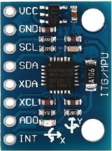
Fig. 1. MPU6050 IMU Sensor
B. TM4C123GH6PM Microcontroller
The TM4C123 is an ARM Cortex-M4F microcontroller with a single-precision FPU, 32 KB SRAM, and 256 KB Flash. It provides hardware peripherals including configurable timers, I2C master, PWM generator, UART, and a CAN 2.0B controller. The system clock is set to 16 MHz from the main crystal oscillator with the FPU enabled for efficient computation.
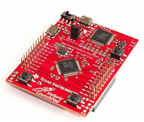
Fig. 2. TM4C123GH6PM LaunchPad
C. I2C Communication
I2C is a two-wire synchronous serial protocol (SCL, SDA) that supports multiple devices on a shared bus with addressing. The TM4C123 I2C0 peripheral operates in fast mode (400 kHz). Each MPU6050 read performs a repeated-start burst receive of 6 bytes, returning accelerometer data for all three axes in a single transaction.
D. Fast Fourier Transform
The FFT converts a time-domain sequence x[n] of N samples into its frequency-domain representation using the Cooley-Tukey radix-2 algorithm:
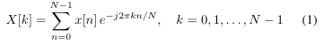
With N = 1024 and fs = 800 Hz, the frequency resolution is fs/N = 0.78 Hz per bin. The implementation uses Q15 fixed-point arithmetic with precomputed twiddle factors stored as 16-bit integers. Butterfly multiplications use 64-bit inter- mediate products to prevent overflow, eliminating all floating- point operations from the real-time loop.
The magnitude of each frequency bin is computed as:
![]()
using an integer square root routine operating on scaled fixed-point values.
E.CAN Bus and MCP2551 Transceiver
Controller Area Network (CAN) is a multi-master differential serial bus designed for robustness in electrically noisy environments. The MCP2551 transceiver converts the TM4C123 CAN controller’s logic-level signals to ISO-11898 compliant differential CANH/CANL signals and supports up to 1 Mb/s. The RS pin (pin 8) must be connected directly to GND to select high-speed mode. Both ends of the CAN bus require 150 Ω termination resistors between CANH and CANL.
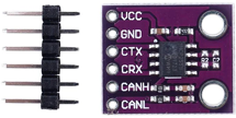
Fig. 3. MCP2551 High-Speed CAN Transceiver
F. L298N Motor Driver
The L298N is a dual H-bridge module that drives a DC motor bidirectionally. Direction is set by the IN1 and IN2 logic inputs; motor speed is controlled by the PWM signal on the Enable pin. It can handle motor supply voltages up to 46 V and continuous current up to 2 A per channel.
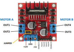
Fig. 4. L298N Dual H-Bridge Motor Driver
G. PWM Speed Control
Pulse Width Modulation controls motor speed by varying the on-time of the enable signal. The TM4C123 PWM0 peripheral (Generator 1, count-down mode) runs at a period of 4000 counts, giving a PWM frequency of 4 kHz at 16 MHz system clock. Motor speed is adjusted by changing the pulse width register.
III.SYSTEM ARCHITECTURE
The overall system architecture is shown in Fig. 5. It consists of two TM4C123 nodes connected by a CAN bus at 500 kbps. Fig. ?? shows the physical hardware setup used during testing.
A. Motor Node (Board 1)
Board 1 is responsible for all sensing, signal processing, and motor control:
1) Acquire tri-axial accelerometer data at 800 Hz via a hardware timer ISR.
2) Buffer 1024 samples per axis.
3) Perform a 1024-point FFT on each axis and average over a 2-window sliding history.
4) Extract peak magnitudes at 57 Hz (bearing) and 25 Hz (imbalance) and compare against thresholds.
5) Apply tiered motor protection based on fault type and consecutive confirmation count.
6) Transmit an 8-byte CAN telemetry frame every process- ing cycle containing FFT magnitudes and motor RPM.
7) Receive and execute operator commands (pause, resume, hard reset) from the Monitor Node.
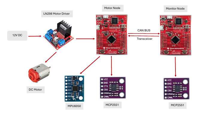
Fig. 5. System Architecture of the Two-Node Motor Fault Detection System
B. Monitor Node (Board 2)
Board 2 provides remote observation and operator control:
- Receive CAN telemetry from Board 1 every FFT cycle (approximately 56 s).
- Mirror the fault detection logic locally (digital twin) and print results to UART at 115200
- Monitor a 4-second CAN watchdog; indicate connection loss with a solid red LED if no frame arrives.
- Respond to pushbutton inputs: SW1 toggles pause/resume; SW2 performs a hard reset of both
C.CAN Message Protocol
Table I defines the CAN message identifiers and payload formats used by both nodes.
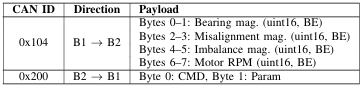
TABLE I MCP2551 CAN MESSAGE IDS AND PAYLOADS
TABLE II CAN COMMAND CODES (BOARD 2 →BOARD 1)
IV.DETAILED ANALYSIS OF TM4C123-BASED EMBEDDED SYSTEM
A. Circuit Schematic
Fig. 6 shows the complete circuit schematic for Board 1 (Motor Node), including the MPU6050 I2C interface, L298N PWM motor driver connections, and MCP2551 CAN transceiver wiring. The schematic for Board 2 (Monitor Node) is identical in the CAN transceiver section, with the MPU6050 and L298N omitted and pushbutton inputs added on PF0 and PF4.
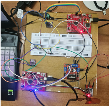
Fig. 6. Circuit Schematic — Board 1 (Motor Node). Shows TM4C123 connections to MPU6050 (I2C0: PB2/PB3), L298N motor driver (PWM: PB4, DIR: PB5/PC4), and MCP2551 CAN transceiver (CAN0: PE4/PE5) with 150Ω bus termination
B. Peripheral Connections — Board 1 (Motor Node)
Table III summarises all pin assignments on Board 1.
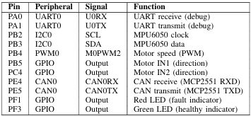
TABLE III BOARD 1 PIN CONFIGURATION (MOTOR NODE)
C. Peripheral Connections — Board 2 (Monitor Node)
Table IV summarises all pin assignments on Board 2.
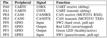
TABLE IV BOARD 2 PIN CONFIGURATION (MONITOR NODE)
D. MCP2551 CAN Transceiver Wiring
The same transceiver circuit is replicated on both boards. Table V lists the required connections, which are critical for correct CAN bus operation.
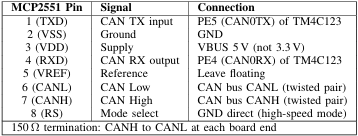
TABLE V MCP2551 PIN CONNECTIONS (PER BOARD)
E. MPU6050 Register Configuration
Table VI lists the sensor registers written during initialisation.
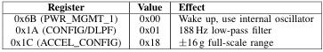
TABLE VI MPU6050 INITIALISATION REGISTERS
F. Timer Configuration
Both boards use hardware timers for time-critical operations. Table VII summarises the timer assignments.
![]()
TABLE VII TIMER PERIPHERAL ASSIGNMENTS
G. PWM Configuration
The motor speed PWM is generated by the TM4C123 PWM0 peripheral on Board 1. Table VIII summarises the configuration and operating duty cycles.
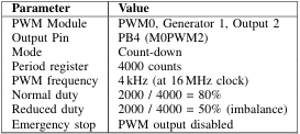
TABLE VIII PWMCONFIGURATION (BOARD 1 — MOTOR NODE)
V.ARCHITECTURAL DESIGN STRATEGIES
A. Fixed-Point FFT
The FFT is implemented entirely in integer arithmetic using Q15 format, where the value 1.0 is represented as 32767. Twiddle factors (cosine/sine pairs) are computed once at startup using floating-point cos() and sin() from the C standard library, then stored as 16-bit integers. All subsequent FFT operations use integer multiply-accumulate with 64-bit intermediate products, ensuring no floating-point instructions execute in the real-time loop. This yields deterministic and repeatable execution time on the Cortex-M4.
An important bug was corrected during development: the twiddle sine table stores − sin(θ) (to simplify the butterfly formula). An earlier version of the code negated this value again at the point of use, effectively restoring + sin(θ) and producing incorrect butterfly outputs across the entire trans- form. Removing the second negation corrected all FFT results.
B. Interrupt-Driven Sampling
Timer0A generates an interrupt at 800 Hz. The ISR reads all three accelerometer axes via I2C burst transfer and stores the results into three sample buffers. After 1024 samples are collected, the ISR sets a flag and halts further sampling until the main loop resets the index. The index and flag are reset atomically under a global interrupt disable to prevent a race condition where the ISR could begin overwriting a buffer still being processed by the FFT.
The ISR also checks the I2C error register after every transaction. If a bus error is detected, a separate flag is set and the ISR returns immediately. The main loop detects this flag, resets the I2C peripheral, and reinitialises the sensor, avoiding an infinite hang inside the ISR.
C. Multi-Axis Sliding Window Averaging
Each FFT processing cycle runs the transform independently on the X, Y, and Z axis buffers. The magnitude of each frequency bin from all three axes is divided by three and summed into a history buffer for the current window slot. After two windows have been collected, the final per- bin magnitude used for fault detection is the average of the two most recent window slots. This 2-window sliding average suppresses single-cycle noise spikes while keeping detection latency to approximately 2.56 s.
Memory optimisation: history buffers use 16-bit integers (uint16_t) rather than 32-bit, saving approximately 2 KB of SRAM compared to a naïve implementation. Table IX summarises the full SRAM budget.
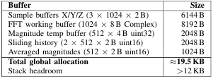
TABLE IX SRAM BUDGET (BOARD 1 — 32KB TOTAL)
D. Fault Detection
Mechanical faults in rotating machines produce character- istic frequency components in the vibration spectrum. This system monitors two fault frequencies, selected based on the motor’s operating characteristics. Table X lists the monitored frequencies, corresponding FFT bins, and detection thresholds.
![]()
TABLE X FAULT FREQUENCIES, BINS, AND DETECTION THRESHOLDS
For each fault frequency, the peak magnitude within ±2 bins of the nominal bin is extracted to tolerate slight frequency variation. Detection priority is bearing > imbalance. The two fault types follow different confirmation and protection policies as described in Section V-E.
E. Tiered Fault Confirmation and Motor Protection
The system implements a tiered protection strategy that distinguishes between bearing faults (critical, immediate dan- ger) and imbalance (moderate, progressive degradation). The confirmation window count and motor response differ for each fault type.
Bearing fault (57 Hz): Bearing defects produce impulsive, rapidly worsening vibration. The system applies a strict 2- window confirmation:
- Window 1 threshold exceeded: WARNING state, no motor change.
- Window 2 threshold exceeded: FAULT CONFIRMED — motor halted immediately (PWM disabled, IN1 LOW).
The motor remains halted until an explicit RESTART command is received from Board 2 via CAN.
Imbalance fault (25 Hz): Rotor imbalance is a progressive condition. The system uses a graduated 5-window response:
- Window 1 threshold exceeded: WARNING state, no motor change.
- Window 2 threshold exceeded: FAULT CONFIRMED — duty cycle reduced to 50% (2000/4000 counts).
- Windows 3–4 threshold still exceeded: motor continues at 50% duty, UART alert repeated.
- Window 5 threshold exceeded: CRITICAL — motor halted immediately (PWM disabled).
If the imbalance clears at any point (magnitude falls below threshold), the fault counter resets and normal 80% duty is restored.
Table XI summarises the complete motor protection state machine.
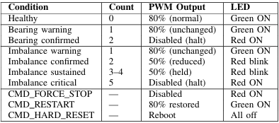
TABLE XI MOTOR PROTECTION STATE MACHINE
F. Digital Twin on Monitor Node
Board 2 implements an identical copy of the fault detection thresholds and confirmation logic, operating on the FFT magnitudes received over CAN. This allows Board 2 to independently determine the motor health state and display it via UART without relying on Board 1 to transmit a pre- classified fault code. If Board 1 fails or the bus is lost, the watchdog timer detects the disconnection within 4 seconds and flags a connection error.
VI.SOFTWARE ALGORITHM
The main loop on Board 1 (Fig. 7) executes the following sequence on each iteration:
- Check the I2C error flag; if set, reset and reinitialise the I2C peripheral and sensor.
- Poll the CAN receive buffer for incoming commands from Board 2 and execute any received command.
- Wait for the sampling-complete flag set by the Timer0A
- Run the 1024-point FFT on each of the three sample axes in sequence.
- Accumulate per-axis magnitudes into the current sliding- window history slot.
- Advance the history index; once two windows are filled, compute the per-bin sliding average.
- Extract peak magnitudes at 57 Hz (bearing) and 25 Hz (imbalance).
- Apply tiered fault confirmation: bearing halts at count 2; imbalance reduces speed at count 2 and halts at count
- Pack bearing magnitude, imbalance magnitude, and motor RPM into an 8-byte CAN frame and transmit on ID 0x104.
- Reset the sample index and ready flag atomically to allow the ISR to begin the next acquisition.
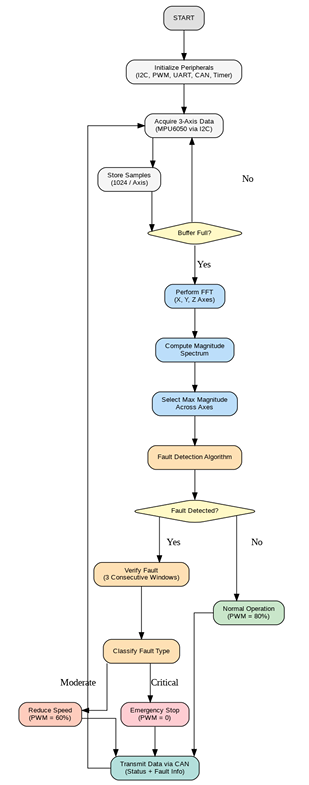
Fig. 7. Software Algorithm Flowchart — Board 1 (Motor Node)
VII.TECHNICAL CHALLENGES AND SOLUTIONS
- CAN bus instability (board reset loops and unreliable communication): Initial instability and Board 2 reset loops were caused by transceiver standby issues and improper bus termination. A capacitor on the MCP2551 RS pin charged past 75 VDD, forcing the transceiver into standby mode and causing the CAN peripheral to lose synchronisation. We resolved this by removing the capacitor, grounding the RS pin to keep the transceiver permanently in high-speed mode, and correcting VDD to 5 V as required by the datasheet. Bus stability at 500 kbps was achieved by adding 150 Ω termination resistors (effective 75 Ω) at both ends, which was sufficient to eliminate reflections over our short cable length.
- FFT sign error in twiddle factors: The twiddle sine table stores − sin(θ) to simplify the Cooley-Tukey butterfly formula. An earlier implementation applied a second negation at the point of use, restoring + sin(θ) and corrupting the phase of all frequency The fix was to use the table value directly without sign inversion.
- DC offset removal before FFT: When the MPU6050 accelerometer reads raw values, the output contains a constant DC offset due to the gravity component acting on the sensor and inherent sensor bias. If this offset is not removed before the FFT, it appears as a large spike at bin 0 (0 Hz), which bleeds energy into nearby low-frequency bins through spectral leakage, corrupting the fault magnitude readings. We resolved this by computing the mean of all 1024 samples and subtracting it from every sample before loading them into the FFT input buffer, ensuring zero mean input and eliminating DC-induced leakage.
- Fault counter never reaching confirmation: The original fault confirmation logic reset the counter to zero whenever the FFT returned a healthy result. Because FFT magnitudes fluctuate between windows, the sequence “fault, healthy, fault, healthy” repeated indefinitely and the counter never reached the confirmation threshold. The fix was to reset the counter only when the detected fault type changes, not on every healthy
- ISR race condition on sample buffer: The sample index (g_idx) and ready flag (g_ready) were originally reset in two separate statements in the main If the Timer0A ISR fired between the two assignments, it could observe a cleared flag but a non-zero index and begin writing into an already partially-processed buffer. Both variables are now reset together inside a global interrupt disable/enable pair.
- I2C peripheral hang on sensor glitch: The original I2C read was a blocking loop with no error checking. A single NACK or bus collision caused the loop to spin indefinitely, preventing the ISR from returning and halting the system. Error checking was added after every I2C master command; on any error the ISR sets a flag and returns. The main loop detects the flag, performs a peripheral reset, and reinitialises the sensor without requiring a system reboot.
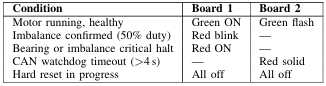
TABLE XII LED BEHAVIOUR ON BOTH BOARDS
VIII.RESULTS AND OBSERVATIONS
A. Healthy Motor Operation
This section presents the UART terminal logs from the Motor Control Node (Board 2), demonstrating the system’s real-time response to operational states and fault conditions transmitted via the CAN bus. Figure 8 shows the terminal output during normal healthy motor operation, where FFT magnitudes remain below all fault thresholds.
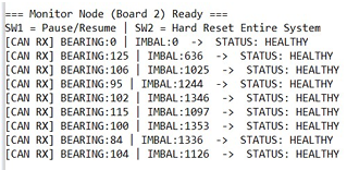
Fig. 8. UART output indicating healthy motor operation
B. Motor Pause Command
Figure 9 shows the UART output confirming successful reception and execution of the pause command transmitted from Board 2 to Board 1 via CAN ID 0x200. Upon receiving the command, Board 1 immediately disables the PWM output and enters the emergency stop state.
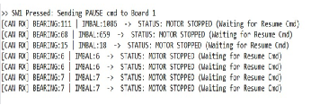
Fig. 9. UART output confirming the motor pause command
C. Motor Resume Command
Figure 10 shows the system response after the resume command is issued from Board 2. The fault counters are cleared, PWM is re-enabled at normal duty cycle, and the system returns to healthy monitoring state.
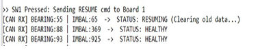
Fig. 10. UART output confirming the motor resume command
D. Bearing Fault Detection and Emergency Halt
Under a bearing fault condition, the system requires two consecutive FFT window confirmations before taking protective action. Figure 11 shows the terminal output at the point of confirmation, after which the motor is immediately halted by disabling the PWM output.
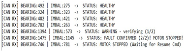 Fig. 11. Motor Stop executed due to Bearing Fault detection
E. Imbalance Fault Detection and Speed Reduction
Under an imbalance fault condition, the system first reduces the PWM duty cycle to 50% as a protective measure while continuing fault monitoring. Figure 12 shows this intermediate speed reduction state, after which a full halt is triggered if the fault persists across subsequent confirmation windows.
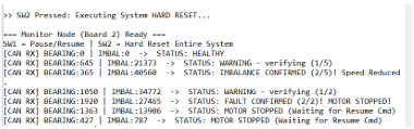
Fig. 12. Speed Reduction and Fault Monitoring during an active imbalance
IX.CONCLUSION
This project successfully developed a deterministic, real- time motor fault detection system on resource-constrained embedded hardware, proving that reliable condition monitoring is achievable without a real-time operating system (RTOS) or floating-point computation. By processing complex vibration signatures directly at the edge, the system provides a highly scalable predictive maintenance in industrial environments.
A two-node distributed system was implemented using TM4C123GH6PM microcontrollers. The Sensor Node acquires tri-axial vibration data at 800 Hz and computes a 1024- point fixed-point FFT (Q15 arithmetic) to accurately isolate bearing defects (57 Hz) and rotor imbalance (50 Hz) with a 0.78 Hz resolution. A key feature of this design is its tiered protection policy: critical bearing faults trigger an immediate motor halt, while less severe imbalance faults initiate a 50% speed reduction, minimizing unnecessary production down- time.
The Monitor Node acts as a remote digital twin via a 500 kbps CAN bus, offering real-time UART diagnostics, bidirectional control, and fail-safe protection through a 4- second hardware watchdog. Overcoming significant hardware and software challenges—including ISR race conditions, FFT twiddle factor errors, and CAN transceiver faults—further validated the robustness of this bare-metal design. Ultimately, this work provides a scalable, practical, and low-cost solution for predictive maintenance in industrial automation.
X.FUTURE SCOPE
While the current architecture establishes a robust foundation for real-time condition monitoring, several avenues exist for future enhancement:
- Direct Memory Access (DMA): Transitioning the I2C sensor data acquisition to a DMA-driven architecture would significantly reduce CPU utilization, allowing for higher sampling rates and larger FFT windows.
- Adaptive Thresholding: Replacing the static amplitude thresholds with a statistical baseline learning algorithm would allow the system to self-calibrate to the baseline vibrations of different motor types.
- Machine Learning Integration: Expanding the rule- based decision logic to incorporate lightweight machine learning models (TinyML) on the Cortex-M4 could enable complex, multi-class fault classification.
- Network Scalability: Extending the two-node CAN architecture into a multi-node industrial network would allow a single monitor node to oversee a factory floor of multiple interconnected motors.
REFERENCES
- InvenSense, MPU-6000 and MPU-6050 Product Specification, 3.4, 2013.
- Texas Instruments, TivaTM TM4C123GH6PM Microcontroller Data Sheet, SPMS376E, 2014.
- Microchip Technology, MCP2551 High-Speed CAN Transceiver Data Sheet, DS20001667G, 2016.
- Robert Bosch GmbH, CAN Specification Version 0, 1991.
- W. Cooley and J. W. Tukey, “An algorithm for the machine calculation of complex Fourier series,” Mathematics of Computation, vol. 19, no. 90, 297–301, 1965.
- B. Randall and J. Antoni, “Rolling element bearing diagnostics – A tutorial,” Mechanical Systems and Signal Processing, vol. 25, no. 2, 485–520, 2011.
- Scheffer and P. Girdhar, Practical Machinery Vibration Analysis and Predictive Maintenance. Elsevier, 2004.
- K. Jalan and A. R. Mohanty, “Model based fault diagnosis of a rotor–bearing system for misalignment and unbalance under steady-state condition,” Journal of Sound and Vibration, vol. 327, no. 3-5, pp. 604– 622, 2009.
- Hariharan and P. S. S. Srinivasan, “Vibration analysis of misaligned shaft–ball bearing system,” Indian Journal of Science and Technology, vol. 2, no. 9, pp. 45–50, 2009.
Recent Comments