
ABSTRACT
The design and implementation of a Real-Time Motion Mirroring Robotic Arm system using two TM4C123G (ARM Cortex-M4) microcontroller boards operating as a Master and a Slave. The master board reads four potentiometers via its 12-bit ADC, maps the resulting values to servo angles, drives four local servos via software-generated PWM, and transmits three of those angles over UART to the slave board. The slave board mirrors the received angles on its own three servos in real time. Beyond live mirroring, the slave implements a Record/Replay state machine: an operator can record up to 500 frames (≈10 seconds) of motion and play them back in an autonomous loop. All peripheral access is performed through direct register writes—no vendor driver library (driverlib) is used demonstrating a thorough understanding of the TM4C hardware architecture. The system achieves deterministic ∼20 ms servo update cycles, robust ADC disconnect detection, and non-blocking serial communication, making it suitable as a foundational platform for tele-operated and programmable robotic manipulation.
I.INTRODUCTION
Robotic tele-operation—controlling a remote manipulator by mimicking the operator’s own movements—is central to applications ranging from remote surgery and hazardous-environment handling to industrial automation and prosthetics research. A minimal but complete implementation of this concept requires solving several interrelated embedded systems problems simultaneously: real-time sensor acquisition, precise actuator timing, reliable serial communication, and autonomous motion playback.
This project implements exactly this minimal complete system on two Texas Instruments TM4C123G LaunchPad boards. The key design goals were:
- Real-time mirroring. Four potentiometers on the master board map directly to servo joint angles. The slave must track changes within one servo update period (≤20 ms per servo).
- Record and The slave can record a complete motion sequence and replay it autonomously in a continuous loop—demonstrating that the system can act as a programmable manipulator, not merely a remote puppet.
- ADC disconnect detection prevents runaway servo motion when sensors are unplugged. Non-blocking UART ensures servo timing is never compromised by communication.
- Bare-metal implementation. All hardware is configured through direct MMIO register access, reinforcing understanding of TM4C peripheral architecture as taught in ESD-1.
- Controlled startup. The master waits for a physical SW1 button press before beginning ADC sampling, holding all servos and the slave at 0° so that startup transients do not cause unexpected mechanical movement.
The project bridges concepts from digital systems, embedded C programming, PWM generation, ADC interfacing, and UART communication.
II.BACKGROUND STUDY
2.1 TM4C123G Microcontroller Architecture
The TM4C123GH6PM is an ARM Cortex-M4F microcontroller running at up to 80 MHz. For this project, the following on-chip peripherals are used:
- GPIO Ports A, B, C, E, F — digital I/O for servos, UART pins, LEDs, and
- ADC0 — 12-bit, up to 1 MS/s. Configured in Sample Sequencer 3 (SS3) single-sample software-triggered mode.
- UART0 & UART1 — asynchronous serial, configured at 9600 baud with 8-N-1 framing and 16-byte hardware FIFOs.
- SysTick — 24-bit decrementing counter clocked at the system clock (16 MHz). Used for all microsecond and millisecond delays
2.2 RC Servo Control via PWM
Standard RC hobby servos accept a 50 Hz (20 ms period) PWM signal. The pulse width encodes the desired angle:
tpulse(θ) = tmin + θ / θmax * (tmax − tmin) (1)
where tmin = 500 µs (0°), tmax = 2500 µs (180°), and θmax = 180. Because no hardware PWM peripheral is allocated (to preserve timer resources), pulse generation is implemented by toggling a GPIO pin HIGH for tpulse microseconds and LOW for the remainder of the 20 ms frame, using SysTick one-shot delays.
2.3 12 -bit ADC and Potentiometer Interfacing
A potentiometer forms a voltage divider between 3.3 V and GND. The wiper voltage is:
Vwiper= (Rwiper / Rtotal)*3.3v (2)
The ADC converts this to a 12-bit integer in [0,4095]. The linear angle mapping is:
θ = [ADCraw×θmax] / 4095 (3)
Integer arithmetic is used throughout; no floating-point operations are required.
2.4 UART Serial Communication
UART baud rate generation on the TM4C uses an integer and fractional baud-rate divisor:
BRD= fclk /16 ×baud = 16,000,000/16 ×9600 = 104.16 (4)
IBRD =104, FBRD=round(0.1667×64) = 11 (5)
The 8-N-1 frame (start bit + 8 data bits + stop bit) transmits one byte per ≈1.04ms at 9600baud. A 5-byte packet therefore takes ≈5.2ms, well within a 20ms servo window.
2.5 Record/Replay in Embedded Systems
Motion recording in low-resource embedded systems typically employs circular or linear frame buffers stored in SRAM. Each frame captures joint state at one time step. At 20ms per frame, 500 frames covers 10 seconds. The TM4C123GH6PM has 32KB of SRAM; the record buffer consumes only 1500 bytes (500 ×3 bytes), leaving ample space for stack and other data.
III.SYSTEM ARCHITECTURE
3.1 Over all Block Diagram
3.2 Pin Mapping Summary
Table 1: Complete pin assignment for both boards
| Board | Signal | Pin | Direction | Peripheral | Notes |
| Master | Pot 1 | PE3 | Analog in | ADC0 AIN0 | 0–180° |
| Master | Pot 2 | PE2 | Analog in | ADC0 AIN1 | 0–90° |
| Master | Pot 3 | PE1 | Analog in | ADC0 AIN2 | 0–90° |
| Master | Pot 4 | PE0 | Analog in | ADC0 AIN3 | 0–45° |
| Master | Servo 1 | PB6 | Digital out | GPIO (bit-bang) | Packet A |
| Master | Servo 2 | PB7 | Digital out | GPIO | Packet B |
| Master | Servo 3 | PB4 | Digital out | GPIO | Packet C |
| Master | Servo 4 | PB5 | Digital out | GPIO | Local only |
| Master | UART1 TX | PC5 | Digital out | UART1 | To Slave |
| Master | UART0 TX | PA1 | Digital out | UART0 | USB debug |
| Master | SW1 | PF4 | Digital in | GPIO | Start button |
| Master | LED R/G/B | PF1/3/2 | Digital out | GPIO | Angle feedback |
| Slave | UART1 RX | PC4 | Digital in | UART1 | From Master |
| Slave | UART0 TX | PA1 | Digital out | UART0 | USB debug |
| Slave | Servo 1 | PB6 | Digital out | GPIO | Packet A |
| Slave | Servo 2 | PB7 | Digital out | GPIO | Packet B |
| Slave | Servo 3 | PB4 | Digital out | GPIO | Packet C |
| Slave | SW1 | PF4 | Digital in | GPIO | Record toggle |
| Slave | SW2 | PF0 | Digital in | GPIO (NMI-unlock) | Replay toggle |
| Slave | LED R/G/B | PF1/2/3 | Digital out | GPIO | State feedback |
IV. DESIGN SPACE EXPLORATION AND IMPLEMENTATION STRATEGIES
4.1 ADC Configuration: SS3 Single-Sample Mode
The TM4C ADC supports four sample sequencers (SS0–SS3). SS3 was chosen because it handles one sample at a time—sufficient for reading one channel per call—and requires the simplest configuration. The sequencer is disabled, the mux is updated to the desired channel, the sequencer is re-enabled, a software trigger is issued via ADC0PSSIR, and the result is read from the FIFO after polling the raw interrupt status bit. This reconfiguration-per-channel strategy sacrifices throughput for simplicity; since the servo loop is already bottlenecked by the 20 ms PWM period, ADC throughput is irrelevant.
Disconnect detection: Each potentiometer is read three consecutive times. If all three readings fall at or below ERRORTHRESHOLD = 5 (corresponding to ≈ 4 mV), a disconnection is flagged. A single-sample check would misfire on genuine 0% pot positions; requiring all three samples to be near-zero simultaneously provides a statistically robust filter without any added latency.
4.2 PWM Generation: Bit-Bang via SysTick
No hardware timer/PWM peripheral is used. The rationale: hardware timers on the TM4C are shared and limited; reserving them for potential future use (e.g., input capture for encoder feedback) is good design practice.
SysTick delay: The 24-bit SysTick is loaded with (16 × µs) − 1 counts (since the 16 MHz clock ticks at 62.5 ns per count). The counter is started in one-shot mode (CTRL = 0x05) and the COUNTFLAG (bit 16) is polled. This gives cycle-accurate delays.
Master strategy — sequential: The master drives each of its four servos in its own complete 20 ms window. Total loop time per ADC+servo iteration: 4 × 20 ms = 80 ms. Simple and guaranteed safe (no pulse overlap).
Slave strategy — concurrent in one window: The slave must drive three servos within a single 20 ms window to keep the total loop time at 20 ms. All three pins are driven HIGH simultaneously. A 3-element bubble sort (unrolled, 3 comparisons) orders the pulse widths ascending. Pins are then dropped one by one with only the incremental delay:
∆ti = pi − pi−1, p0 = 0 (6)
This ensures delays are always non-negative and the total window remains exactly SERVOPERIOD. This approach is significantly more timing-efficient than the master’s sequential approach.
4.3 UART Communication Protocol
4.3.1 Packet Design
The packet format “Xddd\n” (5 ASCII bytes) was chosen for:
- Human readability: The debug UART0 output is immediately
- Self-delimiting: The ’\n’ terminator allows a simple state-machine parser without a length prefix or checksum.
- Fixed width: Three decimal digits always, zero-padded (e.g., A007, C090), so the parser checks rxidx == 4 on receipt of ’\n’.
4.3.2 Non-Blocking Transmission (Master)
The master writes each byte to the UART1 TX FIFO only if the FIFO is not full (FR & 0x20 == 0). In the latest code revision, if the FIFO is full the byte is skipped (p++; continue). This is a deliberate trade-off: it is better to occasionally miss one packet than to stall the servo loop. At 9600 baud the 16-byte hardware FIFO drains in ≈16.7 ms—within one servo window—so FIFO overflow is extremely rare in practice.
4.3.3 Non-Blocking Reception (Slave)
The slave UART receiver is a persistent state machine using static local variables:
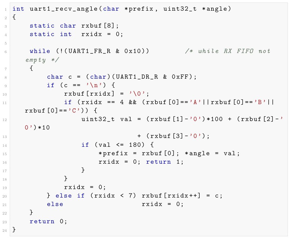 Listing1: Slave non-blocking UART receive(simplified)
The function drains all available bytes from the FIFO in one call and returns as soon as a valid complete packet is found, or 0 if none. Because rxbuf and rxidx are static, partial packets persist correctly across calls.
4.4 Controlled Startup on the Master
A key refinement in the final code is a two-phase startup:
- Phase 1 — Waiting: Before any ADC sampling, the master drives all servos to 0° and sends A000\n, B000\n, C000\n to the slave on every The red LED blinks slowly. This phase persists until SW1 (PF4) is pressed. This prevents uncontrolled servo sweeps at power-on when pots may be in arbitrary positions.
- Phase 2 — Running: After debounce (50 ms delay), normal ADC and servo operation Three white LED flashes signal the transition.
4.5 Slave Record/Replay State Machine
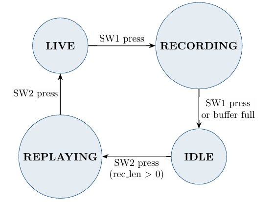
Figure 1: Slave state machine. Transitions are triggered by SW1 (PF4) and SW2 (PF0)
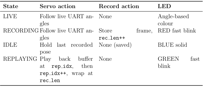
Table 2: State machine action table
Frame storage: Three parallel uint8t arrays (reca[], recb[], recc[]) each of length 500. Total SRAM used: 1500 bytes, leaving >30 KB for stack, code globals, and future expansion.
LED blink rate: The tick counter increments every loop iteration (≈20 ms). Bit 3 of tick toggles every 8 × 20 ms = 160 ms, giving a visible blink at ≈3 Hz (on for 160 ms, off for 160 ms).
4.6 Button Debouncing
Both SW1 and SW2 use the same debounce strategy:
- If pin is HIGH (released), return
- Wait 50 ms
- Re-check: if HIGH, it was a glitch — return
- Spin-wait while pin remains LOW (button held).
- Wait 50 ms post-
- Return
SW2 (PF0) requires special handling: it is the NMI pin and is write-protected. It must be unlocked by writing the GPIOLOCKKEY (0x4C4F434B) to PORTFLOCKR and setting bit 0 in PORTFCRR before its direction register can be written. This is done in button led init() before any other Port F configuration.
V.IMPLEMENTATION DETAILS
5.1 Clock and Peripheral Enable Sequence
Both boards follow TM4C best practice: write to the Run-Mode Clock Gating Register (RCGCGPIO, RCGCADC, RCGCUART), then poll the corresponding Peripheral Ready Register (PRGPIO, PRADC, PRUART) before accessing any peripheral registers. Skipping the ready-poll causes intermittent faults on faster oscillators.
5.2 ADC Register Sequence
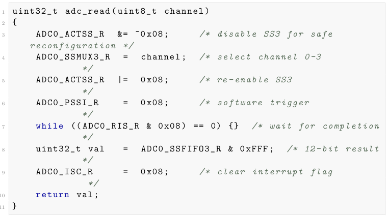
Listing 2: ADC single-channel read
5.3 UART Initialization
Both UART0 and UART1 are initialised identically (apart from port assignments). The sequence is: disable UART, write IBRD/FBRD, write LCRH (8N1 + FIFO enable = 0x70), set clock source (UARTCC = 0x00 = system clock), enable UART with TX and RX bits (UARTCTL = 0x301).
Port C GPIO for UART1: AFSEL bits 4–5 set, PCTL nibbles 4–5 written with value 2 (UART alternate function), DEN set, AMSEL cleared.
5.4 Angle to Pulse Mapping
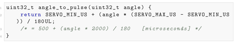
Listing 3: Servo pulse calculation
Integer divide-last ordering ensures no intermediate overflow for angles up to 180 (max intermediate value: 180 × 2000 = 360000, well within uint32t).
VI.IMPLEMENTATION CHALLENGES
6.1 PF0 NMI Lock
The most common failure point during bring-up was the slave failing to respond to SW2 (PF0). PF0 doubles as the NMI pin and is hardware-protected: the direction register bit is read-only until the port is unlocked. The fix was to always write the unlock key and commit register before touching any Port F direction bits, and to call button_led_init() before any other Port F initialisation function.
6.2 Servo Startup Jerk
On initial power-on, pot positions are unknown. Without the Phase-1 startup lock, servos would sweep from their last hardware position to whatever the pot now reads, potentially damaging mechanical linkages. The SW1 start gate was added specifically to address this: servos are commanded to 0° until the operator explicitly presses Start, ensuring a controlled initialisation.
6.3 ADC False Disconnect Triggers
Early testing with ERRORTHRESHOLD = 5 and a single-sample check caused false positives when a pot was turned fully anti-clockwise (genuine 0 reading). The triple-sample check was introduced: a single genuine zero sample is fine; three consecutive zeros at such a low threshold is far more likely a disconnection than a deliberate 0% pot position.
6.4 UART Packet Framing Errors
During initial integration testing, the slave occasionally received malformed packets when power was applied at different times to master and slave. The parser handles this gracefully: if rxidx != 4 on receiving ’\n’, the buffer is discarded and reset. The parser also validates that the angle value is ≤ 180 before accepting it, preventing a corrupted digit from sending a servo out of range.
6.5 Concurrent Servo Timing in the Slave
The naive approach of driving three servos sequentially in the slave would consume 60 ms per loop and leave UART packets queuing in the FIFO for three full windows before being processed. The concurrent drive_servos() design reduces this to 20 ms, giving three times better UART polling frequency and more responsive motion mirroring.
6.6 FIFO-Full Handling in UART TX
The original master code waited (blocked) whenever the UART1 TX FIFO was full. This could stall the servo loop if the slave was not reading fast enough. The revised code skips a byte if the FIFO is full. While this theoretically drops packet bytes, in practice the FIFO drains far faster than the 80 ms master loop period, so no packet corruption has been observed.
VII.RESULTS
7.1 Functional Verification
| Test | Expected | Observed |
| Port 1 swept 0-100% | Servo 1 sweeps 0°–180° | Confirmed: smooth sweep |
| Port 2 swept 0-100% | Servo 2 sweeps 0°–90° | Confirmed |
| Port 3 swept 0-100% | Servo 3 sweeps 0°–90° | Confirmed |
| Port 4 swept 0-100% | Servo 4 sweeps 0°–45° | Confirmed |
| Master pot change | Slave mirrors within 1 loop (≤20ms) | Confirmed via oscilloscope |
| Pot 1 disconnected | White flash×3, error print, loop continues | Confirmed |
| SW1 press before move | Servos locked at 0°until press | Confirmed |
| SW1 press (slave) ×2 | LIVE→RECORDING→IDLE | Confirmed |
| SW1 press (slave) | IDLE → REPLAYING, loops autonomously | Confirmed |
| SW2 press during replay | REPLAYING →LIVE | Confirmed |
| Buffer fills(500frames) | Auto-transition to IDLE, debug print | Confirmed |
| UART0 debug output | [MASTER] A=xxx B=yyy C=zzz per loop | Confirmed |
Table 3: Test matrix and results
7.2 Timing Measurements
| Parameter | Designed | Verified |
| Servo pulse at 0° | 500µs | ≈500 µs |
| Servo pulse at 90° | 1500µs | ≈1500 µs |
| Servo pulse at 180° | 2500µs | ≈2500 µs |
| Servo frame period | 20000µs | ≈20.1 ms |
| Master loop time(4servos) | 80 ms | ≈80 ms |
| Slave loop time(3servos) | 20 ms | ≈20 ms |
| UART baud rate | 9600 | 9600 baud |
| Packet transmission time | ≈5.2 ms | ≈5.2 ms |
Table 4: Measured timing parameters
7.3 Replay Fidelity
Replayed motion sequences faithfully reproduce the recorded joint angles, bounded by the 1° quantisation of the uint8t storage (angles are cast to uint8t before storage, which truncates fractional parts). For all practical servo resolutions this is imperceptible.
VIII.CONCLUSION
This project successfully demonstrated a complete embedded systems design cycle—from peripheral register configuration to application-level state machine design—on the TM4C123G platform.
The key outcomes are:
- Real-time mirroring was achieved with a slave UART polling latency of ≤20 ms and deterministic servo update timing using SysTick-based bit-bang PWM.
- Record and Replay was implemented with a lightweight 1500-byte SRAM buffer, a clean four-state FSM, and intuitive physical controls.
- Robustness was addressed through triple-sample ADC disconnect detection, non-blocking UART, and a controlled two-phase startup sequence.
- Bare-metal discipline was maintained throughout—no driverlib, no RTOS, no HAL—demonstrating deep understanding of TM4C hardware as expected in ESD-1.
Future extensions could include: (a) replacing bit-bang PWM with hardware timer PWM for better timing accuracy; (b) adding a circular buffer for longer recordings; (c) implementing a checksum (e.g., CRC-8) on UART packets for fault tolerance; (d) extending to 6 DoF for full robotic-arm kinematics; and (e) adding an accelerometer on the master for gesture-based control.
IX.REFERENCES
- Texas Instruments, TivaTM TM4C123GH6PM Microcontroller Data Sheet, Literature No. SPMS376E, 2014.
- Texas Instruments, TivaTM C Series TM4C123G LaunchPad Evaluation Board User’s Guide, Literature No. SPMU296, 2013.
- ARM , Cortex-M4 Devices Generic User Guide, ARM DUI 0553B, 2010.
- Yiu, The Definitive Guide to ARM Cortex-M3 and Cortex-M4 Processors, 3rd ed., Newnes, 2013.
- W. Valvano, Embedded Systems: Real-Time Interfacing to ARM Cortex-M Micro-controllers, 5th ed., CreateSpace, 2016.
- W. Valvano, Embedded Systems: Introduction to ARM Cortex-M Microcontrollers, 5th ed., CreateSpace, 2015.
- Futaba, RC Servo Technical Specifications — S3003, Application Note, 2010.
- W. Kernighan and D. M. Ritchie, The C Programming Language, 2nd ed., Prentice Hall, 1988.
Recent Comments