
ABSTRACT
This project presents the design and development of a basic drone flight control system using an embedded microcontroller platform. The system is built around the TM4C123GH6PM (Tiva C) microcontroller, which interfaces with a radio frequency (RF) receiver to interpret throttle, yaw, roll and pitch control inputs transmitted from a remote controller. These PWM inputs are decoded as signals and processed to gen-erate appropriate control signals for Electronic Speed Controllers (ESCs) that drive the four brushless DC (BLDC) motors.
An Inertial Measurement Unit (IMU) – MPU6500, is integrated to provide real-time orientation and motion data, including roll, pitch, and yaw. These values enable the implementation of closed-loop control using PID algorithms for stabilizing the drone during flight. The system demonstrates fundamental concepts of embedded systems, including signal decoding, sensor interfacing, real-time control, and actuator management.
I.INTRODUCTION, MOTIVATION AND LEARNING OUTCOMES
1.1 Introduction
Unmanned Aerial Vehicles (UAVs), commonly known as drones, have become increasingly important in modern ap-plications such as surveillance, delivery systems, agriculture, and environmental monitoring. At the core of any drone lies a flight control system that ensures stable and responsive operation. This project focuses on developing a fundamental drone control architecture using an embedded systems approach.
1.2 Motivation
The motivation behind this project is to gain practical knowledge of embedded systems by applying theoretical concepts to a real-world application. Drone systems combine multiple domains, including signal processing, sensor interfacing, control systems, and real-time programming, making them an ideal platform for hands-on learning. By building a drone control system from scratch, we aim to understand how individual components—such as micro-controllers, sensors, and actuators interact to achieve stable flight.
1.3 Learning Outcomes
The key learning outcomes from this project are as follows:
- Learning how to write complex programs using bare metal coding style.
- Gain hands-on experience with the TM4C123GH6PM (Tiva C) microcontroller for real-time embedded application
- Learn how to decode and generate PWM signals for con-trolling Electronic Speed Controllers (ESCs) and BLDC
- Develop skills in interfacing sensors, specifically IMU modules (MPU6500/MPU9250), to obtain motion and orientation data.
- Apply concepts of control systems, particularly PID control, for stabilizing dynamic systems like drones.
- Integrate multiple hardware components and software modules into a cohesive embedded system.
- Improve debugging and testing skills for both hardware and firmware in a real-time environment.
- Understand the challenges involved in system calibration, synchronization, and achieving stable operation.
The overall system level block diagram is shown below:
II.MAJOR COMPONENTS
The major components used in the projects are listed below:
2.1 TM4C123GH6PM
Microcontroller: TM4C123GH6PM (Tiva C Series Launch-Pad) based on ARM Cortex-M4 architecture. It performs real time processing, PID computation, and PWM generation for motor control.
2.2 Electronic Speed Controllers (ESCs)
This is fully programmable 30A BLDC ESC with 5V, 3A BEC. Can drive motors with continuous 30Amp load current. It has sturdy construction with 2 separate PCBs for Controller and ESC power MOSFETs. It can be powered with 2-4 lithium Polymer batteries or 5-12 NiMH / NiCd batteries. It has separate voltage regulator for the microcontroller for providing good anti-jamming capability. It is most suitable for UAVs, Aircrafts and Helicopters.
Four ESCs (20A typical) used to drive the brushless DC motors. They receive PWM signals from the microcontroller.
2.3 MPU6500
The MPU-6500 is a 6-axis Motion Tracking device that combines a 3-axis gyroscope, 3-axis accelerometer, and a Digital Motion Processor™ (DMP) all in a small 3x3x0.9mm package. It also features a 512-byte FIFO that can lower the traffic on the serial bus interface, and reduce power consumption by allowing the system processor to burst read sensor data and then go into a low-power mode. With its dedicated I2C sensor bus, the MPU-6500 directly accepts inputs from external I2C devices. MPU-6500, with its 6-axis integration, on chip DMP, and run-time calibration firmware, enables manufacturers to eliminate the costly and complex selection, qualification, and system level integration of discrete devices, guaranteeing optimal motion performance for consumers. MPU-6500 is also designed to interface with multiple non-inertial digital sensors, such as pressure sensors, on its auxiliary I2C port.
2.4 BLDC-A2212/13T (Quadcopter use)
The BLDC-A2212/13T is a commonly used brushless motor for small quadcopters in the 800–1200 g range, typically powered by 3-cell (3S) Li-Po batteries. It provides a good balance between thrust and efficiency, making it suitable for stable flight and basic maneuvering.
The motor is generally paired with 9”–10” propellers, allowing sufficient lift for hovering and light payload applications. Its lightweight design, dual ball bearings, and standard mount-ing configuration make it easy to integrate into quadcopter frames, while pre-attached connectors simplify interfacing with the electronic speed controller (ESC).
2.5 Flysky receiver
The Flysky FS-iA6B is a compact 2.4 GHz radio receiver designed for RC applications such as multi copters, helicopters, and fixed-wing aircraft. It operates using the AFHDS 2A (Automatic Frequency Hopping Digital System) protocol, ensuring reliable and interference-resistant communication. The FS-iA6B is a lightweight, low-latency receiver offering multiple output protocols and reliable long-range communication, making it suitable for hobbyist and entry-level UAV/RC systems.
2.6 LiPo Battery
3S LiPo battery (11.1V) used to power the ESCs and motors. A regulated 3.3V/5V supply is used for the micro-controller and sensors.
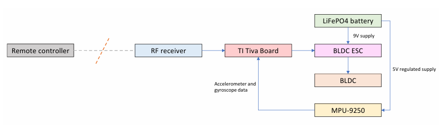
Fig. 1: Block diagram of the quadrotor drone
III. ARCHITECTURE SETUP
The high level circuit schematics for the drone which involves the TI Tiva evaluation board, MPU-6500, 4 ESCs (Electronic Speed Controllers), 4 BLDCs, Flysky receiver, LiPo battery is shown in the figure below. As shown in the image, Port C GPIO pins are connected to the FLysky i6 receiver. The MPU-6500 is connected to Port A pins configured in SSI mode. The ESCs are connected to four of Port B PWM hardware pins.
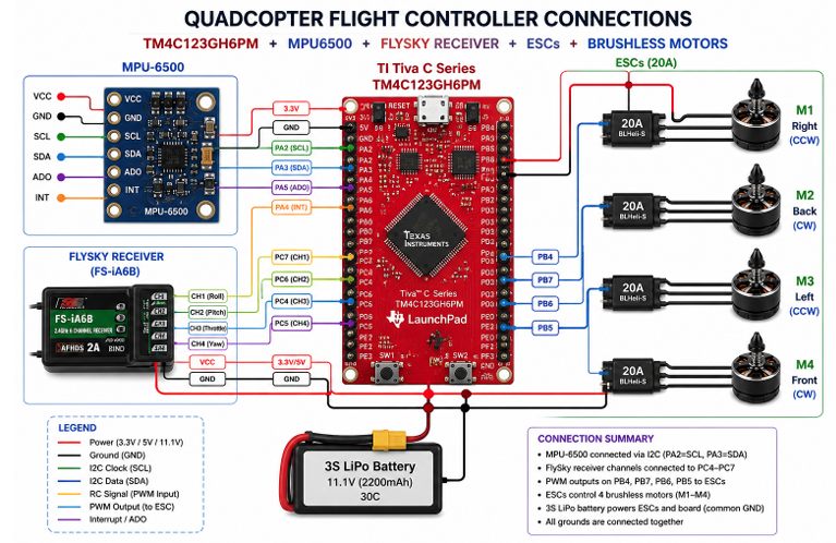
Fig. 2: components arrangement
IV. WORKING PROCESS OF DRONE
4.1 Power ON and Initialization
When the system is powered using a LiPo battery, the micro-controller initializes all peripherals such as GPIO, SPI, PWM, and interrupts. The IMU sensor is configured, and calibration is performed to remove offset errors in the gyroscope and accelerometer.
4.2 RC Receiver Input
The RC receiver sends control signals (throttle, roll, pitch, and yaw) as PWM pulses to the microcontroller. These signals are captured using GPIO interrupts and converted into digital values representing user commands.
4.3 IMU Sensor Measurement
The IMU (MPU-6500) measures:
- Linear acceleration (accelerometer)
- Angular velocity (gyroscope)
These values are read by the microcontroller using the SPI communication protocol.
4.4 Sensor Fusion (Angle Estimation)
The raw sensor data is processed using a complementary filter to estimate:
- Roll angle
- Pitch angle
Yaw is estimated by integrating gyroscope data over time.
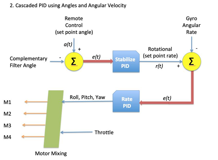
4.5 PID control
The estimated angles are compared with desired setpoints (from the RC input). The error is processed using a PID controller, which generates correction signals to stabilize the drone.
4.6 Motor Mixing
The PID outputs are combined with throttle input to calculate individual motor speeds based on the quadcopter (+ configuration).
4.7 ESC Control
PWM signals are sent to the Electronic Speed Controllers (ESCs), which regulate the power supplied to each motor.
The motors adjust their speeds accordingly:
- Increasing speed → more thrust
- Decreasing speed → less thrust . This differential thrust stabilizes the drone and enables movement in roll, pitch, and yaw directions.
V. MOTOR CONFIGURATION
Motor mixing is the process of converting the control signals generated by the PID controller into individual motor speed commands. Since a quadcopter has four motors, the total thrust and directional control (roll, pitch, yaw) are achieved by appropriately varying the speed of each motor.
- Front motor → Pitch control
- Back motor → Pitch control
- Left motor → Roll control
- Right motor → Roll control
- Yaw controlled via motor torque differences
In a plus (+) configuration, each motor contributes differently to motion along different axes. The throttle provides the base speed for all motors, while the PID outputs for roll, pitch, and yaw are added or subtracted to generate differential thrust.
The motor speeds are calculated as follows:
ESCfront = T − pitch − yaw
ESCback = T + pitch − yaw
ESCleft = T + roll + yaw
ESCright = T − roll + yaw
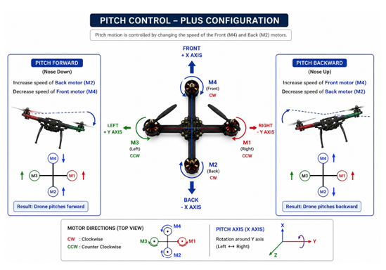
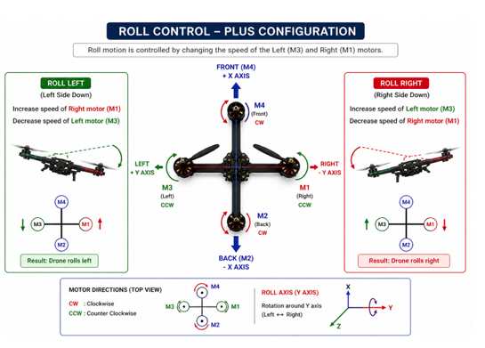
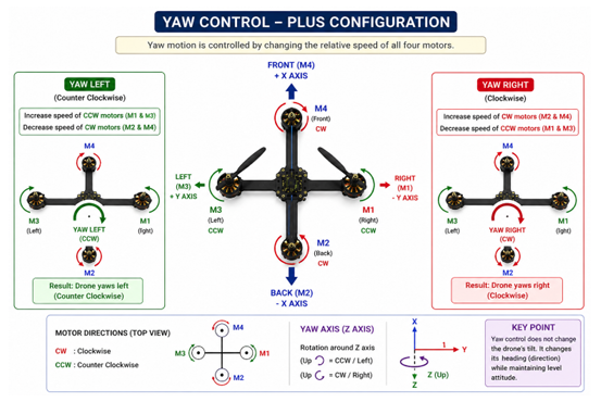
Fig. 3: Pitch, Roll, Yaw configuration
VI. SENSOR PROCESSING
The microcontroller communicates with the IMU using SPI, where it acts as the master and the IMU acts as the slave. The master sends register addresses through MOSI and receives sensor data (acceleration and gyro values) through MISO, synchronized with the clock (SCLK) and controlled by the CS signal.
- Accelerometer → Angle estimation
- Gyroscope → Angular velocity
- Complementary filter combines both 8cm(8.5cm,4.0cm) [ θ = 0.999 (θ + ω · dt) + 0.001 · θacc]
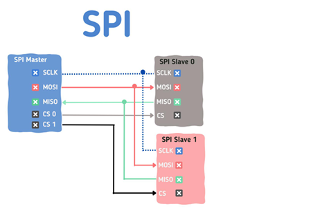
Fig. 4: SPI protocol
VII. CALIBRATION
Calibration is the process of removing sensor offsets to ensure accurate measurements from the IMU. During calibration, the drone is kept stationary on a flat surface. The gyroscope bias is calculated by averaging multiple samples when there is no motion. Similarly, accelerometer offsets are computed to correct tilt errors. These offset values are stored and subtracted from real-time sensor readings. This ensures that the measured angles correspond to a true zero reference position. Proper calibration helps in reducing drift and improves stability during flight. It is essential to perform calibration before every flight for reliable performance.
VIII. PID CONTROLLER
PID control is the core stabilizing mechanism that continuously corrects orientation errors using IMU feedback. The IMU provides current roll and pitch angles (and gyro rates).
These are compared with desired setpoints from the RC receiver → producing an error.
- Proportional (P): Immediate correction
- Integral (I): Removes steady-state error
- Derivative (D): Damping and stability
The PID controller continuously compares desired angles with measured angles from the IMU and generates correction signals. These corrections adjust motor speeds through a closed-loop system to maintain stable flight
The PID controller converts orientation errors into motor speed adjustments to stabilize the drone in real time.
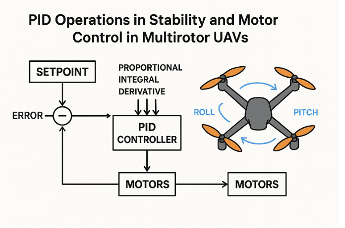
The PID controller stabilizes the drone by continuously correcting its orientation through a closed-loop control system that compares the desired orientation with the actual orientation measured by the IMU sensor.
IX. PID CONTROLLER TUNING
Step 1: Tuning Proportional Gain (Kp)
- Increase Kp gradually
- Observe tilt correction
- Increase until slight oscillations appear
- Reduce slightly to stabilize
Observation:
- Low Kp : Slow response
- High Kp : Oscillations
Step 2: Tuning Derivative Gain (Kd)
- Increase Kd gradually
- Helps reduce oscillations
- Adjust for smooth response
Observation:
- Low Kd : Overshoot
- High Kd : Noisy or jittery response
Step 3: Tuning Integral Gain (Ki)
- Increase Ki slowly
- Eliminates steady-state error
- Corrects long-term drift
Observation:
- Low Ki : Persistent error
- High Ki : Slow oscillations (windup)
X. SOFTWARE ARCHITECTURE
- 4 ms control loop
- Interrupt-based RC reading
- SPI-based sensor communication
- PWM hardware output
XI. WORKING OF CODE
11.1 System Overview
The implemented system integrates sensor data acquisition, signal processing, control algorithms, and motor actuation within a fixed control loop to achieve stable flight. A comple-mentary filter combines accelerometer and gyroscope readings to obtain stable roll and pitch angles. These measured angles are compared with desired setpoints derived from user input, and the error is processed through PID controllers for each axis. The PID outputs are then mixed appropriately based on the quadcopter configuration to generate individual motor speed commands. These commands are sent as PWM signals to the electronic speed controllers (ESCs), which drive the brushless motors. All operations are executed within a time-critical loop of approximately 4 ms, ensuring consistent control updates and stable flight behavior.
11.2 Hardware Interface Initialization
- SysTick (Global Timer): 24-bit down counter used for microsecond timing. Clock = 16 MHz (system clock), no prescaler. Used to implement micros(), delay_us(), and loop timing.
- GPIO Initialization Ports configured for:
PF1 (Red), PF3 (Green) → status LEDs
PC4–PC7 → RC input channels (interrupt-based)
PA2–PA5 → SPI interface
PB4–PB7 → PWM outputs (ESC control)
- PWM for ESCs (PWM0 Module) PWM clock = 16 MHz / 64 = 250 kHz Period = 20 ms → LOAD = 4999 Resolution = 4 µs per tick Pulse width:
CMP = 5000 −( pulse width µs / 4)
Range: 1000–2000 µs for ESC control.
- SPI0 (IMU Communication) Configured in master mode, 8-bit transfer, Mode 0 (CPOL=0, CPHA=0). Clock = 16 MHz / 32 = 500 kHz. Manual chip select using GPIO (PA3).
- RC Input Capture (GPIO Interrupts) PC4–PC7 con-figured for both-edge interrupts. Pulse width measured using timestamp difference:
Pseudo-code for RC Capture:
on rising edge: t_start = time
on falling edge:
width = time – t_start
if valid:
store value
11.3 Sensor Initialization and Calibration
- MPU-6050 Configuration
- Initialized via SPI
- Power register set to wake mode using PLL with X-axis
- Digital Low Pass Filter configured to ∼43 Hz to reduce noise.
- Gyroscope range set to ±500
- Accelerometer range set to ±8
- Configuration verified by reading back register
- Gyroscope Calibration
- Performed at start up when the drone is
- 2000 samples of gyro data are
- Average offset computed for each axis
- Offsets subtracted from raw gyro readings during operation
- Accelerometer Offset Calculation
- Accelerometer used to estimate initial roll and pitch
- 2000 samples averaged to compute steady-state
- Offsets applied in complementary filter for drift correction.
Pseudo-code for Calibration:
for i = 1 to 2000:
read gyro, accel
sum gyro values
compute accel angles
sum angles
gyro_offset = sum / 2000
acc_offset = angle_sum / 2000
11.4 RC Signal Processing
- Interrupt-Based Pulse Width Measurement
- RC signals received as PWM pulses (1000–2000 µs).
- GPIO pins (PC4–PC7) configured for both-edge inter-
- Rising edge → timestamp
- Falling edge → pulse width computed using time difference
- Valid pulse widths (900–2100 µs) are accepted
- Channel Mapping and Normalization
-
- Raw pulse widths are clamped to 1000–2000 µ
- Channels mapped as:
CH1 → Roll
CH2 → Pitch
CH3 → Throttle
CH4 → Yaw
-
- Neutral position centered around 1500 µ
- Small dead-band applied to avoid noise near
11.5 IMU Data Processing
- Raw Sensor Data Acquisition
- IMU data (MPU-6050) read via SPI in burst
- 14 bytes fetched:
- Accelerometer: ax, ay, az
- Temperature (ignored in control)
- Gyroscope: gx, gy, gz
- Data converted from 16-bit registers to signed
- Axis Mapping and Sign Correction
- Sensor axes remapped to match quadcopter
- Sign adjustments applied to ensure correct rotation direc-
- Gyroscope offsets (calibrated earlier)
- Final variables:
- gyroroll, gyropitch, gyroyaw
- accx, accy, accz
- Complementary Filter for Angle Estimation
- Gyroscope used for short-term angular rate integration:
θ = θ + ω · dt
Accelerometer used for long-term drift
- Complementary filter combines both:
θ = 0.999 · θgyro + 0.001 · θacc
- Yaw-induced cross-coupling compensation
- Final outputs:
-
- angle roll
- angle pitch
11.6 Flight Control Logic
11.6 1 Arming and Disarming Mechanism
• Safety feature to prevent accidental motor start.
• Arming sequence:
- Throttle low (< 1050 µs)
- Yaw left (< 1050 µs) → initiate
- Yaw center (> 1450 µs) → arm
• Disarming sequence: – Throttle low– Yaw right (> 1950 µs)
• On arming: – Angles reset– PID integrators cleared
11.6 2 Setpoint Generation from RC Inputs
• Desired roll and pitch derived from RC inputs.
• Dead-band applied around 1500 µs to avoid noise.
• Setpoints scaled down (division by 3) for stability.
• Auto-level correction subtracts measured angle:
setpoint = (input − 1500) − level adjust / 3
• Yaw setpoint enabled only when throttle is above idle
11.7 PID Control Algorithm
11.7.1 Roll Control
• Error computed as:
e =gyro input−setpoint
• Proportional term:
P =Kp·e
• Integral term accumulated over time (with limiting):
I =I+Ki·e
11.7.2 Pitch Control
• Same PID structure as roll axis.
• Uses pitch gyro input and pitch setpoint.
• Independent tuning parameters:– Kp, Ki, Kd
• Output limited to ensure stable actuation.
11.7.3 Yaw Control
• PID applied on yaw rate (not absolute angle).
• Error based on difference between gyro yaw and setpoint.
• Typically lower Kp compared to roll/pitch.
• Integral term helps reduce steady-state drift.
• Output constrained to avoid excessive rotation.
11.8 Motor Mixing and Output Generation
Plus Configuration Mixing
• Control signals (throttle, roll, pitch, yaw) combined to generate individual motor outputs.
• Based on plus (+) configuration:
- Front and back → pitch control
- Left and right → roll control
- Opposite motor pairs → yaw control
- Motor outputs computed as
M1 = T − R + Y
M2 = T + P − Y
M3 = T + R + Y
M4 = T − P − Y
where T = throttle, R = roll, P = pitch, Y = yaw.
Throttle Limiting and Output Constraints
-
- Throttle limited to maximum safe value (e.g., 1800 µs).
- Each motor output constrained within:
1100 ≤ Mi ≤ 2000 µs
- When disarmed:
- All motor outputs set to 1000 µs (minimum).
Final outputs converted to PWM compare values and written to ESCs
11.9 Main Control Loop
1) Loop Timing and Synchronization
• Control loop runs at fixed interval of 4 ms (250 Hz).
• Timing maintained using micros() from SysTick.
• Loop waits until 4000 µs elapsed before next iteration.
• Overrun condition detected if execution exceeds 4050 µs.
2) Sensor Update and Control Execution
• Each loop iteration performs:
- Read IMU data (gyro + accelerometer)
- Update orientation (complementary filter)
- Read and process RC input
- Generate setpoints
- Compute PID outputs
- Perform motor mixing
- Update ESC PWM signals
Ensures deterministic and stable control behavior
11.10 Safety and Status Indication
1) LED Indicators
• PF1 (Red LED):
- ON during initialization and calibration
- Blinks while waiting for valid RC input
- Indicates error or unsafe condition
• PF3 (Green LED):
- ON when system is ready and armed
Indicates normal operation
2) Loop Overrun Detection
• Monitors execution time of control loop.
• If loop exceeds 4050 µs:– Red LED is turned ON as warning.
• Otherwise: – Green LED remains ON during normal operation.
• Helps detect timing violations affecting stability
XII. EXPERIMENTAL RESULTS AND VALIDATION
12.1 ESC PWM Signal Analysis (Logic Analyzer)
The PWM signals generated by the flight controller and sent to the ESCs were captured using a logic analyzer as seen in the images below. The signals exhibit a fixed period of approximately 20 ms (50 Hz), with pulse widths varying between 1000–2000 µs depending on control inputs.
• Idle: all motors at minimum pulse width.
• Roll/Pitch: differential variation across motors.
• Throttle: uniform increase across all motors.
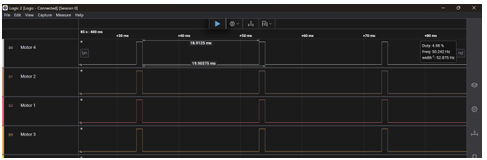 Fig. 5: ESC PWM signals under idle condition
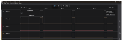 Fig. 6: ESC PWM signals increased throttle
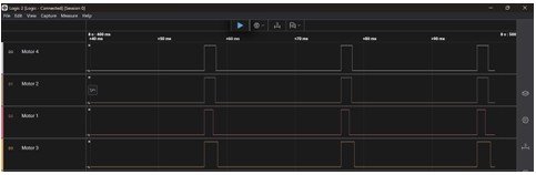 Fig. 7: Motor response during roll left
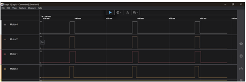 Fig. 8: Motor response during roll Right
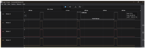 Fig. 9: Motor response during pitch up
 Fig. 10: Motor response during pitch down
12.2 Flight Testing
The quadcopter was tested under controlled conditions to validate stability and control performance. The system demonstrated stable hovering and appropriate response to control inputs.
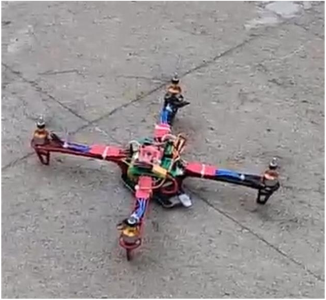
Fig. 11: Quadcopter during flight testing
This project successfully demonstrated the implementation of a quadcopter flight control system using the TM4C123GH6PM microcontroller. Key functionalities such as PWM signal generation for ESCs, interrupt-based RC signal decoding, SPI-based IMU interfacing, and real-time PID control were implemented and verified.
The logic analyzer results confirmed correct generation of ESC control signals, with appropriate pulse width variation corresponding to throttle, roll, and pitch inputs. This validates the correctness of the signal processing, control logic, and motor mixing implementation.
However, stable flight performance was limited due to incomplete PID tuning and system-level calibration. Achieving reliable flight requires careful tuning of PID gains, precise sensor calibration, and mechanical balancing of the quadcopter frame.
With further tuning of the control parameters and refinement of the calibration process, the system is expected to achieve significantly improved stability and sustained flight performance. Overall, the project provides a strong foundation for developing a fully stable and responsive quadcopter control system
XIII. REFERENCES
[1] F4b1-, YMFC-AL Flight Controller (Improved Version), GitHub repository. Available: https://github.com/F4b1-/YMFC-AL-Flight-Controller-improved
[2] J. Brokking, YMFC-AL: Arduino Auto-Level Flight Controller. Available: http://www.brokking.net/ymfc-al main.html
[3] J. Brokking, YMFC-32 Quadcopter Project. Available: http://www.brokking.net/ymfc-32 main.html
[4] InvenSense, MPU-6000 and MPU-6050 Product Specification, 2013.
[5] K. Ogata, Modern Control Engineering, 5th ed., Prentice Hall, 2010.
[6] R. Mahony, V. Kumar, and P. Corke, Multirotor Aerial Vehicles: Modeling, Estimation, and Control, IEEE Robotics & Automation Magazine, 2012.
Recent Comments