
ABSTRACT
In modern high-voltage electrical environments, the ability to instantly detect and respond to sustained power faults is critical for system safety. This project details the design and implementation of an interrupt-driven real time power monitoring and protection system utilizing the ARM Cortex-M4 based Tiva C (TM4C123G) platform.
Keywords: ARM Cortex-M4, TM4C123G, ADC Interrupts, Power Monitoring, RMS Calculation, Energy Tracking, Fault Protection, Galvanic Isolation.
I.INTRODUCTION AND MOTIVATION
Electrical power monitoring is a foundational requirement in industrial automation, smart grid technologies, and consumer safety devices. Standard power strips and thermal circuit breakers react to faults using physical bi-metallic strips or slow-melting fuses. While effective for catastrophic shorts, these mechanical systems lack the intelligence to monitor sustained, low-level power overloads or provide real-time telemetry such as cumulative energy consumption.
Traditionally, microcontroller-based smart monitors handle this by polling sensors in a continuous software loop. However, this “polling” architecture exposes the system to dangerous vulnerabilities. If the CPU is occupied performing heavy floating-point math or communicating over UART, the sampling frequency drifts, ruining the accuracy of the AC RMS calculations.
The system acquires analog data from a ZMPT101B voltage transformer and an ACS712 Hall-effect current sensor, scaling the 230V AC mains to the 3.3V operational domain utilizing isolated hardware voltage dividers. To guarantee precise sampling without stalling the CPU, the architecture utilizes a SysTick-driven Nested Vectored Interrupt Controller (NVIC) topology to buffer data in discrete time blocks. Featuring dynamic auto-calibration, continuous energy consumption tracking, and a strictly evaluated 15W fault protection scheme, this report validates a highly responsive, deterministic embedded safety monitor.
We set out to engineer a solution by fully decoupling the data acquisition logic from the main application math. By leveraging the SysTick hardware timer and the ADC interrupts of the TM4C123G, we designed a block-processing architecture where discrete blocks of 200 samples are gathered silently in the background. The main loop evaluates this buffer every 100 milliseconds, guaranteeing highly accurate power calculations and rapid fault response.
II.SYSTEM ARCHITECTURE
The system architecture revolves around isolating the high-voltage load switching from the low-voltage calculation domain.
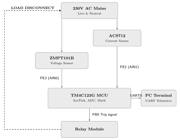 Figure 1: Hardware Architecture and Signal Flow Sequence
2.1 Block-Processing Protection Strategy
Instead of reacting erratically to single noisy samples, the protection logic utilizes a continuous integration approach. The system buffers exactly 200 samples at 2,000 Hz, creating discrete 100ms evaluation windows. Once a buffer is full, the CPU calculates the true RMS power over that block. If the calculated Active Power exceeds the defined 15W threshold, the CPU instantly trips the relay on PB0, guaranteeing a system fault response time of ≤ 0.1 seconds.
III.FIRMWARE IMPLEMENTATION
3.1 SysTick-Driven Data Acquisition
The timing of the analog sampling is managed exclusively by the ARM Cortex-M4 SysTick timer. Configured with a reload value of 7999 (yielding exactly 2,000 Hz on a 16 MHz clock), the timer routinely interrupts the processor to initiate ADC0 Sequence 2.
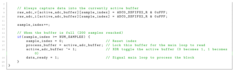
Once the ADC conversion is complete, the ADC0Seq2 arrays. When the 200-sample limit is reached, a data heavy floating-point mathematics. Handler stores the raw voltage and current data into volatile
ready flag is asserted, signalling the main loop to execute the heavy floating-point mathematics.
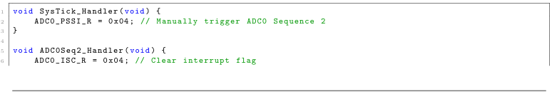
 Listing1: Interrupt Service Routines for Deterministic Sampling
3.2 Energy Accumulation Logic
Because power is the rate of energy transfer, the total energy consumed by the load can be calculated sequentially. The main application loop operates on the data ready flag. Since it processes N=200samples collected at 2000Hz, the time elapsed for each block is exactly ∆t=0.1s.
By maintaining a running sum of the filtered active power every 100ms, the system calculates the cumulative energy consumption and converts it to standard kilowatt-hours(kWh).
![]() Listing 2 : Real-Time Energy Numerical Integration
Listing 2 : Real-Time Energy Numerical Integration
3.3 Firmware: Frequency & Zero-Crossing Detection
•To accurately measure the AC grid frequency, the firmware scans the 200-sample block for positive-going zero crossings.
• It records the array index of the first and last crossing. Since the exact hardware sampling rate is known(2,000 Hz, or 0.5ms per sample), the time span can be perfectly derived.
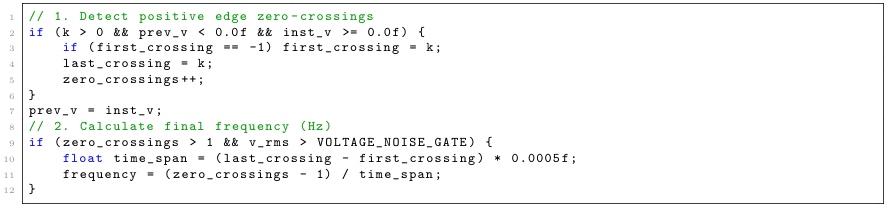 Listing 3: Real-Time Frequency and zero crossing detection and Frequency calculation
3.4 Hardware Floating-Point Optimization
The TM4C123G features an ARMCortex-M4F processor equipped with a hardware Floating-Point Unit(FPU) that strictly supports 32-bit single-precision mathematics. To prevent the compiler from silently promoting calculations to 64-bit double-precision—which forces slow software emulation—all floating-point constants and thresholds are explicitly defined with the f suffix (e.g.,15.0f,4095.0f). This guarantees that the RMS math and continuous energy integration execute natively on the hardware FPU in minimal clock cycles, preserving the deterministic100ms timing constraints.
3.5 System Validation via Parallel Load Testing
To validate the system’s precision and deterministic response, a strict, fail-safe threshold of 15W was hardcoded into the firmware. The validation setup employs a 9W LED bulb and a 12W LED bulb wired in parallel to the PB0 relay output.
By switching the individual loads sequentially, the UART telemetry verifies accurate power tracking and energy accumulation at 9W and 12W respectively, allowing the system to remain armed. However, when both loads are engaged simultaneously, the cumulative 21W draw instantly exceeds the 15W threshold. This safely and predictably triggers the software protection, asserting the PB0 signal to disconnect the AC load. Once the system enters this hardware-locked fault state, it mimics a strict industrial circuit breaker, alerting the user via the UART terminal: ’texttt*** FAULT: POWER OVERLOAD. RELAY TRIPPED! ***.’
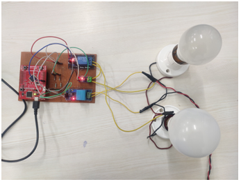
IV.HARDWARE PROTOTYPE AND PHYSICAL IMPLEMENTATION
4.1 Overall Hardware setup
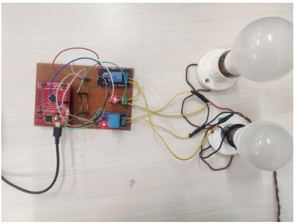 Figure 2: Overall Hardware Setup
4.2 When only 12W LED is connected
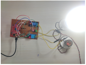 (a) Hardware setup
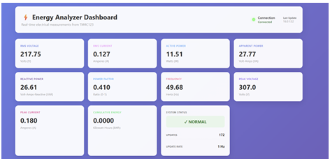
(b) Readings on Web-based GUI Dashboard
Figure 3: When 12W LED is connected; and dashboard showing real time readings with 11.27W real power
4.3 When two LEDs are connected
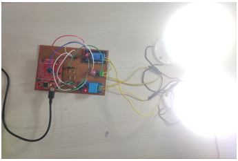 (a) Hardware setup
 (b) Readings on Web-based GUI Dashboard
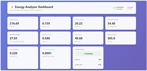
Figure 4: When two LEDs of 9W and 12W are connected; and dashboard showing real time readings with 20.22W real power
4.4 When two LEDs are connected with threshold of 15V
 (a) Hardware setup
 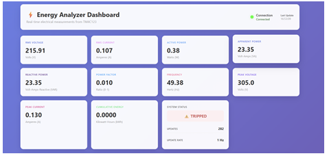 (b) Readings on Web-based GUI Dashboard
Figure 5: When two LEDs of 9W and 12W are connected with set threshold of 15W; and dashboard showing real time readings Tripped status
V.IMPLEMENTATION CHALLENGES
5.1 Dynamic Offset Compensation
Analog sensors exhibit natural DC offsets based on manufacturing variances and temperature. Rather than hardcoding these baselines, a two-pass algorithm was developed for every 100ms block. Pass 1 averages the 200 raw samples to dynamically determine the exact DC bias. Pass 2 then subtracts this calculated center point before applying hardware multipliers, ensuring zero-drift accuracy.
5.2 Breadboard EMI and Software Noise Gating
A significant challenge arose during idle testing (0V, 0A physical state). The 12-bit ADC sensitivity, combined with the capacitance of the breadboard tracks, resulted in the sensors acting as high-gain antennas, picking up 50Hz electromagnetic interference (EMI) from the ambient environment. This manifested as phantom voltage and current readings.
To solve this “phantom loading” where the system accumulates energy while physically disconnected, a two-stage approach was utilized. First, the physical hardware was migrated from a breadboard to a soldered perf board to drastically reduce parasitic capacitance. Second, an aggressive software “Noise Gate” was integrated to clamp any remaining calculated RMS micro-fluctuations to zero:
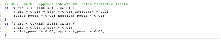 Listing 4: Digital Noise Gate Filter
This digital filtering successfully stabilized the baseline terminal output to a perfect zero, preventing false energy accumulation while maintaining full sensitivity for real high-voltage AC waveforms.
VI.FUTURESCOPE
While the current prototype successfully validates the core deterministic DSP protection logic, future iterations can N scale this architecture for wider deployment:
• Three-Phase Integration: Expanding the ADC channel sampling to simultaneously monitor three-phase industrial power lines.
• Wireless IoT Integration: Replacing the physical UART bridge with an ESP32 co-processor to transmit telemetry to cloud databases (AWS/GCP) via MQTT.
• Custom PCB Fabrication: Transitioning from soldered perfboard to a custom-designed printed circuit board with dedicated ground planes to further minimize analog cross-talk and EMI.
VII.CONCLUSION
By leveraging the SysTick timer and ADC interrupts of the ARM Cortex-M4 architecture, a highly robust power protection system was successfully implemented. The strict decoupling of background data acquisition from foreground RMS math ensures that the system acts as a strict fail-safe circuit breaker while simultaneously functioning as a precision telemetry monitor capable of continuous energy tracking. The inclusion of software noise gates, physical voltage dividers, and dynamic auto-calibration algorithms demonstrates a resilient design capable of mitigating analog hardware limitations through intelligent embedded C programming.
VIII.REFERENCES
[1] Texas Instruments, TM4C123GH6PM Microcontroller Data Sheet, Literature Number: SPMS376E, 2014.
[2] Allegro MicroSystems, ACS712: Fully Integrated, Hall-Effect-Based Linear Current Sensor IC, Datasheet, Rev. 15.
[3] Qingdao Zeming Eletric Co., ZMPT101B Voltage Transformer, Technical Specifications.
[4] Oppenheim, A. V., & Schafer, R. W. Discrete-Time Signal Processing, 3rd ed. Pearson, 2009.
Recent Comments