
ABSTRACT
This report presents the design, implementation, and analysis of a two-wheeled self-balancing robot built on the Texas Instruments TM4C123GH6PM (ARM Cortex) microcontroller. The system employs an MPU-6050 inertial measurement unit (IMU) for real-time tilt sensing, a complementary filter for sensor fusion of accelerometer and gyroscope data, and a PID (ProportionalˆaIntegralˆaDerivative) controller to maintain upright balance. Stepper motors are driven via a software-generated pulse-widthscheme executed inside a 20us Timer0A interrupt service routine. Peripheral subsystems include I2C communication for IMU data acquisition, UART for serial debugging, SysTick for millisecond resolution timekeeping, and Bluetooth (UART2) for remote directional control. The report details the embedded software architecture, interrupt configuration, sensor calibration procedure, PID tuning strategy, and motor control algorithm. The robot successfully achieves dynamic balance under normal operating conditions.
I.INTRODUCTION
Self-balancing robots are a canonical problem in control systems, demonstrating the challenge of stabilizing an inherently unstable inverted pendulum. These platforms find application in personal transportation (e.g., Segway), warehouse logistics, and educational robotics. The control objective is to continuously measure the robotˆ as tilt angle and apply corrective torque through the drive wheels so that the center of mass re
mains above the axle. This project implements a self-balancing robot on the TM4C123GH6PM (Tiva C LaunchPad), a 32-bit ARMCortex-M4F microcontroller clocked at 80 MHz via the PLL. The robot uses an Inven Sense MPU-6050 six-axis IMU to measure tilt, a complementary filter for sensor fusion, and a PID controller that outputs motor speed commands. Two stepper motors, driven by a pulse-frequency modulation scheme inside a 50 kHz timer interrupt, actuate the wheels. The remainder of this report is organized as follows: Section II describes the hardware architecture, Section III details the software design and code structure, Section IV explains the interrupt system, Section V covers the sensor fusion and PID algorithm, Section VI discusses motor control, Section VII outlines the calibration and tuning procedure, and Section VIII
concludes the report.
.
II .SYSTEM ARCHITECTURE
2.1 Microcontroller
The TM4C123GH6PM features an ARM Cortex core running at up to 80 MHz, 256 KB Flash, 32 KB SRAM, hardware floating-point unit, nested vectored interrupt controller(NVIC), and a rich peripheral set including six UARTs, four I2C modules, and six 16/32-bit timers. The system clock is configured for maximum speed using the Phase-Locked Loop (PLL) driven from the on-board 16 MHz crystal: S The system clock is configured for maximum speed using the Phase Locked Loop (PLL) driven from the on-board 16 MHz crystal:
SysCtlClockSet (SYSCTL SYSDIV1 |
SYSCTL USE PLL | SYSCTL OSC MAIN |
SYSCTL XTAL 16MHZ);
2.2 IMUMPU-6050
The MPU-6050 provides three-axis accelerometer and three axis gyroscope measurements over the I2C bus. It is configured at hex address 0x68. To ensure optimal performance for tilt sensing, the internal registers are initialized as summarized in Table 1.
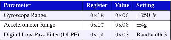
Table 1: MPU-6050 Register Configuration
The Digital Low-Pass Filter (DLPF) is set to bandwidth setting 3 to provide moderate noise reduction while maintaining an acceptable latency for the 250 Hz control loop.
2.3 Motor Drivers and Stepper Motors
Two stepper motors are driven through dedicated motor driver boards. The microcontroller generates step and direction signals on Port A (PA2 to PA5). The step pulse is produced by toggling the step pin high for one 20us cycle and low for the next, resulting in a pulse-frequency modulation scheme where the interval between pulses determines motor speed.
2.4 Communication Interfaces
The system utilizes two UART modules for data exchange and remote control UART0 (PA0/PA1) is configured at 9600 baud to serve as a debug console through the on-board USB-to-serial converter. UART2 (PD6/PD7), also operating at 9600 baud. This setup enables the reception of wireless directional commands from a mobile application.
III.GPIO PIN ALLOCATION
Table 2 summarizes the GPIO pin assignments across all active ports. Port A controls motor step and direction signals. Port B provides the I2C bus for the MPU-6050. Port C hosts the infrared line sensors. Port D carries the Bluetooth UART. Port F drives the RGB status LED and reads the two on-board pushbutton switches.
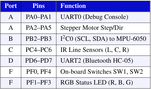 Table 2: GPIO Pin Allocation Summary
IV.SOFTWARE ARCHITECTURE
The firmware is organized into three source files:
• main.c: Contains the control loop, sensor fusion, PID algorithm, and the Timer0A ISR.
• balbot.c: Implements all peripheral initialization functions and the SysTick handler.
• balbot.h: Provides macro definitions, peripheral register addresses, and function prototypes.
The main() function follows a sequential initialization pattern, then enters an infinite super-loop that executes once every 4 ms (250 Hz). The 4 ms timing is enforced by polling a loop
timer variable against the SysTick-based millis() counter:
while ( loop timer > millis ());
l oop timer += 4;
V.INTERRUPT SYSTEM AND TIMING
The system employs two interrupt sources, each with a distinct purpose and priority level. The interrupt priority scheme follows the ARM Cortex-M4 NVIC model, where lower numeric values denote higher urgency.
5.1 SysTick Timer (1 ms)
The SysTick timer is the ARM Cortex-M4’s built-in 24-bit countdown timer. It is configured to fire every 1 ms by loading the reload register with (16,000−1), corresponding to 16,000 clock ticks of the 16 MHz system oscillator:
NVIC ST RELOAD R = 16000 − 1; // 1 ms
NVIC ST CTRL R = 7;
/ / Bit 0: Enable
/ / Bit 1: Interrupt enable
/ / Bit 2: System clock source
The SysTick Handler() ISR increments a volatile global millisCount variable. The millis() function returns this counter, providing a non-blocking millisecond time base used by the main loop to enforce its 4 ms period.
SysTickisassigned priority 1 (second-highest) to ensure accurate timekeeping.
5.2 Timer0A (20 µs — Stepper Motor Pulse Generation)
Timer0A is a 32-bit general-purpose timer configured in periodic countdown mode. It triggers an interrupt every 20 µs (50 kHz), creating the fundamental time quantum for stepper motor pulse generation:
uint32 t load value =
( SysCtlClockGet () / 50000) − 1;
TimerLoadSet (TIMER0 BASE,
TIMER A, load value );
Inside the Timer0A Handler() ISR, a throttle counter for each motor is incremented every 20 µs. When the counter exceeds the current throttle value (set by the PID output), the counter resets, the direction pin is updated, and the step pin is pulsed (set high at count = 1, low at count = 2). This generates a variable-frequency step pulse where lower throttle values produce higher step rates and thus faster motor rotation.
Timer0A is assigned priority 2.
5.3 Interrupt Priority Summary
The interrupt priorities are configured to ensure that critical time-keeping and communication tasks are not preempted by motor control logic. Table 3 provides a summary of the priority levels, execution periods, and specific purposes for each interrupt source.
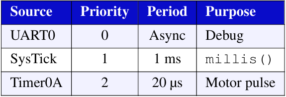 Table 3: Interrupt Priority Configuration
VI.SENSORS
Raw accelerometer and gyroscope data exhibit complementary noise characteristics. The accelerometer provides an absolute tilt reference but is noisy at short time scales. The gyroscope gives smooth angular rate data but drifts over time due to bias integration.
6.1 Accelerometer Angle Calculation
The accelerometer’s Y-axis reading is converted to a tilt angle using the arcsine function. The raw value is first offset corrected using a calibration constant(980LSB)and clamped to ±8200 to prevent domain errors in asin():
accelerometer raw += acc calibration;
// Clamp to valid range
if (accelerometer data raw> 8200)
accelerometer data raw = 8200;
if (accelerometer data raw< −8200)
accelerometer data raw = −8200;
angle acc = asin(( float)
accelerometer data raw / 8200.0)
* 57.296; // rad to deg
6.2 Gyroscope Angle Integration
The gyroscope pitch rate is numerically integrated each loop iteration. At ±250◦/sfull-scale, the raw LSB-to-degrees conversion factor, combined with the 4ms sample period, gives a scaling constant of approximately 0.000031:
gyro pitch data raw −= gyro pitch cal ;
angle gyro += gyro pitch data raw * 0.000031;
6.3 Complementary Filter Fusion
A first-order complementary filter combines the two estimates, weighting 99.96% toward the gyroscope(for short-term smoothness)and 0.04% toward the accelerometer (for long term drift correction):
angle gyro = angle gyro * 0.9996 + angle acc * 0.0004;
The high gyroscope weight is appropriate for this 250Hz loop rate; the accelerometer contribution prevents unbounded drift over minutes of operation. Additionally, they aw gyroscope reading is used to compensate for yaw-induced pitch
coupling during turns.
VII.PID CONTROLLER DESIGN
The PID controller computes a motor drive signal based on the angular error between the filtered tilt angle and the desired set point. The controller implements the standard discrete-time PID law:
u(k) = Kp · e(k) + Ki · ∑e( j) + Kd · [e(k) −e(k − 1)] (1)
where e(k) is the error at sample k.
7.1 Error Computation
The error term incorporates both the target set point and a self
balance correction term. When the PID output magnitude exceeds10(indicating significant corrective effort),a small feed back term(1.5%oftheoutput)is added to the error to prevent integral wind up during aggressive corrections:
pid error temp = angle gyro
− self setpoint
− pid spoint ;
if (pid output >10 || pid output < −10)
pid error temp += pid output * 0.015;
7.2 Integral Term with Anti-Windup
The integral accumulator is clamped to ±400 to prevent integral wind up, which would other wise cause severe over shoot when the robot is held at an angle and then released:
pid i mem += pid i gain * pid error temp;
if (pid i mem> 400) pid i mem = 400;
if (pid i mem< −400) pid i mem = −400;
7.3 Output Calculation and Safety Clamping
The total PID output is computed and clamped to ±400. A dead-zone of ±5 eliminates motor jitter when the robot is near vertical. If the tilt exceeds ±30◦,the system assumes the robot has fallen and disables all outputs:
pid output = pid p gain * pid error temp
+ pid i mem
+ pid d gain
* (pid error temp − pid last d error );
// Clamp and dead−zone
if (pid output > 400) pid output = 400;
if (pid output <5&& pid output > −5)
pid output = 0;
// Fall detection
if (angle gyro>30 || angle gyro< −30)
{ pid output = 0; start = 0; }
7.4 Tuning Parameters
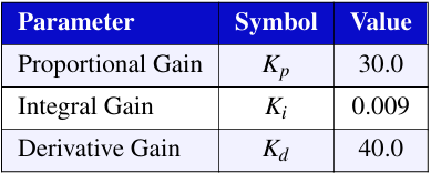 Table 4: PID Tuning Parameters
The high derivative gain(Kd=40) relative to the proportional gain(Kp=30) reflects the need for rapid damping of oscillations. The comparatively low integral gain(Ki=0.009)
provides steady-state correction without introducing significant over shoot.
VIII MOTOR CONTROL ALGORITHM
The PID output (range±400) is transformed into a motor speed value through an online ar mapping that accounts for
stepper motor torque characteristics. The transformation ensures smooth speed transition sat low PID outputs while providing near-full speed at high outputs:
if (pid output left > 0)
pid output left = 405
− (1/(pid output left+9)) * 5500;
else if (pid output left < 0)
pid output left = −405
− (1/(pid output left −9)) * 5500;
This hyperbolic mapping(of the for my=A−B/(x+C)) compresses the output at low values and expands it at high values, effectively linearizing the perceived motor response. The final motor throttle value is calculated as the difference from 400,yielding a count of 20µs intervals between step pulses.
8.1 Timer 0 AISR— Pulse Generation
Inside the Timer 0 A Handler(), each motor’s throttle counter increments every 20µ. When the counter exceeds the throttle memory value, the following occurs in sequence:
(1) the counter resets to zero, (2) the new throttle value from the main loop is latched, (3) the direction pin is set based on sign, and(4) on the next two counts the step pin is driven high then low, generating a single step pulse. The effective step frequency is: fstep = 50000 / throttle value Hz.
IX.I2C COMMUNICATION
The I2C 0 peripheral (PB2=SCL,PB3=SDA) operates in Fast Mode(400kHz).Two utility functions handle all MPU-6050 transactions:
9.1 I2C Write (reg, data)
Performs a two-byte burst write: sends the register address followed by the data byte using I2C MASTER CMD BURST SEND START and I2C MASTER CMD BURST SEND FINISH commands.
9.2 I2C Read Mult i(reg, length)
Performs a multi-byte burst read: first sends the register address as a single write, then switches to read mode and issues START, CONTINUE, and FINISH commands to read the specified number of bytes into the raw Data []buffer. This function reads 2 bytes for the accelerometer and 4 bytes for the gyroscope (yaw+pitch) in each loop iteration.
X.CALIBRATION AND START UP PROCEDURE
The setup MPU6050() function performs a critical calibration sequence at startup. After waking the MPU-6050(writing 0x00 to register 0x6B) and configuring the gyroscope and accelerometer ranges, the function collects 500gyroscopes amples over approximately 2seconds, averaging them to determine the gyroscope bias:
for (i = 0; i < 500; i++) {
I2CReadMulti(0x43, 4);
gyro yaw += (rawData[0]<<8) | rawData[1];
gyro pitch += (rawData[2]<<8) | rawData[3];
delayMs(4);
}
gyro yaw /= 500;
gyro pitch /= 500;
During calibration, the red LED toggles every 15 samples to indicate progress. Upon completion, the green LED illuminates, signalling readiness. The robot must remain stationary
during this calibration phase. The main loop does not begin active balancing until the accelerometer angle reads within ±0.5◦ of vertical, at which point the start flag is set to1and the gyroscope angle is initialized to the accelerometer reading. This prevents large transient errors at start up.
XI.SELF-BALANCE SET POINT ADAPTATION
When no directional commands are active (pid set point=0), the self balance pid set point variable is slowly adjusted to compensate for residual mechanical imbalance or center-of-gravity offset. If the PID output is persistently positive(robot leaning forward), the set point decreases by 0.0015 per iteration; if negative, it increase. This very slow adaptation (≈0.375◦/s) acts as a trimming mechanism that prevents the robot from slowly drifting in one direction when standing still.
XII.CONCLUSION
This report presented a complete embedded systems implementation of a self-balancing two-wheeled robot. The design leverages the TM4C123GH6PM’s peripheral-rich architecture to combine I2C sensor communication, complementary filter-based sensor fusion, a tuned PID controller, and high frequency interrupt-driven stepper motor control into a cohesive real-time system. Key design decisions that contributed to successful balancing include:.
- The 0.9996/0.0004 complementary filter weighting that provides rapid gyroscope response with long-term accelerometer drift correction
- The 20 µs timer interrupt that enables precise pulse frequency control of stepper motors.
- The nonlinear hyperbolic output mapping that linearizes motor torque response.
- The integral anti-windup clamping that prevents over shoot.
The system demonstrates that a PID-controlled inverted pendulum can be effectively realized on a mid-range ARM Cortex-M4 microcontroller with careful attention to interrupt timing, sensor calibration, and control parameter tuning.
REFERENCES
[1] Texas Instruments, TM4C123GH6PM Microcontroller DataSheet, SPMS376E, 2014.
[2] InvenSense Inc., MPU-6000 and MPU-6050 Product Specification, Revision 3.4, 2013.
[3] J. J. Slotine and W. Li, Applied Nonlinear Control, Prentice-Hall,1991.
[4] Texas Instruments, TivaWare Peripheral Driver Library User’sGuide, SPMU298, 2020.
[5] R. C. Dorf and R. H. Bishop, Modern Control Systems, 13th ed., Pearson, 2016.
Recent Comments