
ABSTRACT
As applications such as the Internet of Things expand, the need for secure data transmission between embedded systems becomes critical. While high-end microcontrollers possess dedicated cryptographic hardware, low-cost alternatives like the TM4C123GH6PM require highly optimized software implementations to manage constraints. This project presents a robust, interrupt-driven C library for Advanced Encryption Standard (AES) data encryption, deployed across two TIVA C Series LaunchPads communicating via UART. The system supports parameterized key sizes (128, 192, 256 bits) and multiple operational modes (ECB, CBC, CTR), seamlessly integrating hardware switches, LCD UI, and asynchronous data handling.
I.INTRODUCTION
Microcontrollers form the backbone of modern embedded systems, frequently communicating sensitive telemetry, commands, or user data. Low-cost microcontrollers, such as the TM4C123GH6PM utilized on the TIVA C LaunchPad, possess rich peripheral interfaces (SPI, I2C, UART) but lack dedicated hardware accelerators for cryptographic operations. Consequently, securing data on these platforms requires a software-based encryption engine carefully optimized for time and memory constraints.
The Advanced Encryption Standard (AES) is a symmetric block cipher widely adopted for its resistance to cryptanalytic attacks. In this project, an AES library was engineered from the ground up and integrated into a real-time, event-driven embedded application. The system demonstrates secure board-to-board communication by allowing a user to dynamically parameterize key sizes and cipher modes, type a message asynchronously, and observe the encrypted transmission and decrypted reception in real-time.
II.AES ENCRYPTION & DECRYPTION PRINCIPLES
AES operates on fixed blocks of data—specifically 16 bytes (128 bits) at a time. It utilizes a substitution-permutation network, repeating a specific sequence of mathematical transformations over multiple “rounds”.
II.1 Key Expansion and Rounds
The algorithm accepts cipher keys of 128, 192, or 256 bits. The larger the key, the higher the security against brute-force attacks, but the more computational rounds are required. The initial key is expanded into a key schedule used throughout the encryption process.
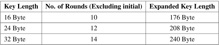 Table 1: AES Rounds and Expanded Key Lengths
During each round (except the final one), the 16-byte state array undergoes four distinct transformations:
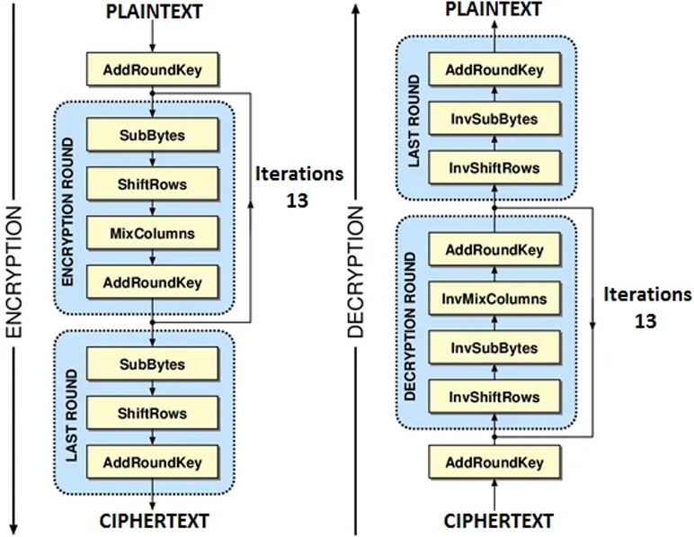
Figure 1: Overall Architecture Flow of the AES Algorithm for ECB and CBC
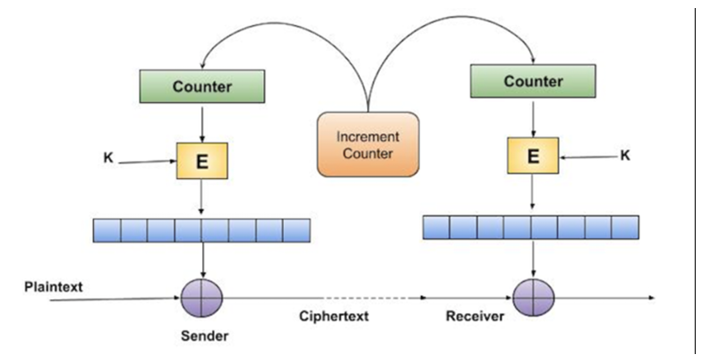 Figure 2: Architecture flow of CTR mode
1. SubBytes: A non-linear substitution using a pre-calculated S-Box lookup table.
2. ShiftRows: A cyclical transposition of the state matrix rows.
3. MixColumns: A mathematical mixing operation utilizing Galois Field multiplication.
4. AddRoundKey: A bitwise XOR operation combining the state with the current round’s key.
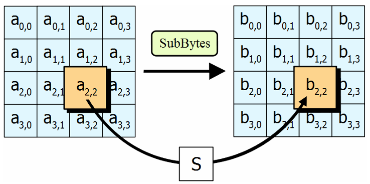 Figure 3: SubByte stage processing
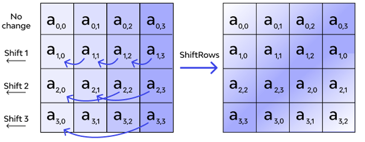 Figure 4: Shift row stage
III .SOFTWARE & HARDWARE IMPLEMENTATION (Code Architecture)
The core achievement of this project is the integration of the AES engine with a real-time, interrupt-driven user interface. The main.c file acts as the conductor, managing physical buttons, an LCD, user terminal input, and board-to-board transmission simultaneously.
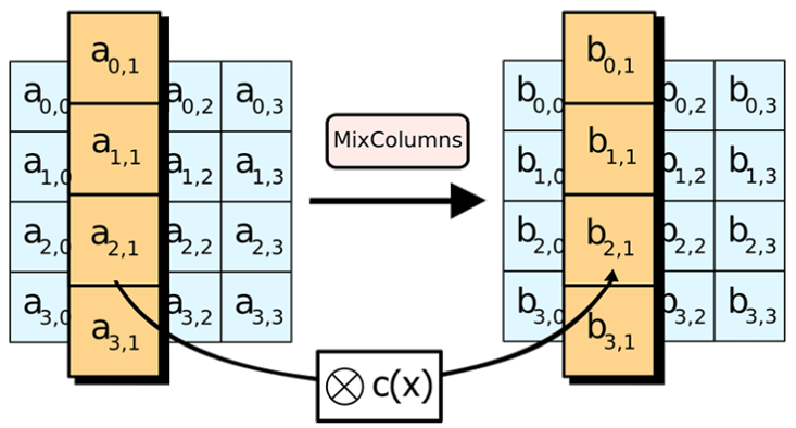 Figure 5: Mix column stage
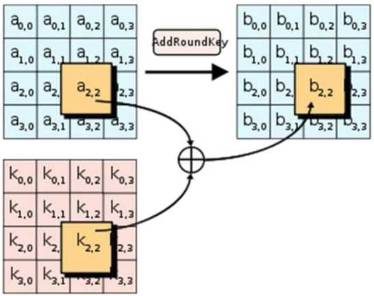 Figure 6: Addround key stage
III.1 Hardware Initialization and Switch Interrupts
Upon booting, the System_Init() function configures the CPU clock to 16 MHz. It initializes Port F for the onboard switches and configures the LCD.
• Mode Selection via SW2 (PF0): Pin PF0 is hardware-locked by Texas Instruments as an NMI(Non-Maskable Interrupt) safety pin. The initialization routine writes the special unlock key (0x4C4F434B) to the GPIO_O_LOCK register to convert it into a standard GPIO input.
• Interrupt Handling & Debouncing: Both switches (PF4 and PF0) are mapped to the GPIOF_IntHandler. To prevent mechanical switch ”bouncing” from causing rapid, erratic mode changes, a software debounce mechanism is utilized: if((msTicks- lastDebounce)> 250).
• Cycling Modes: Pressing SW2 executes currentMode = (currentMode + 1) % 3. This modulo arithmetic cleanly cycles the system state between CTR (0), ECB (1), and CBC(2) modes, immediately printing the new status to the user console.
III.2 LCD Scrolling via SysTick Timer
To provide visual feedback without stalling the CPU, a background timer (SysTick) is configured to interrupt the processor exactly once every millisecond.
• Aglobal msTicks counter increments on every interrupt.
• Every 600 milliseconds, if the isScrolling flag (controlled by SW1) is true, the timer increments the txScrollIdx and rxScrollIdx cursors.
• It then sets lcdUpdateFlag = true. This allows the main foreground loop to safely refresh the LCD using a 13-character strncpy “window” without blocking critical background interrupts.
III.3 Asynchronous User Input (UART0)
Standard C functions like scanf() or gets() are “blocking”—they halt the entire processor until the user hits Enter. In a communications system, halting the CPU means dropping incoming messages.
To solve this, a custom UART0_GetString_Async() function was engineered.
• It runs in a while(1) polling loop, checking UARTCharsAvail() for keystrokes.
• Multitasking: In between checking for key strokes, it constantly monitors the rx Complete flag (to immediately decrypt incoming messages) and the lcdUpdateFlag (to redraw the screen).
• Backspace Support: It explicitly handles ASCII character 127 (Backspace), decrementing the buffer index and transmitting \b \b to visually erase the typo from the user’s terminal
III.4 Foreground Execution: The Encryption Pipeline
The main while(1) loop dictates the user experience and handles the cryptographic packaging:
1. Key Size Prompt: The system requests a key size, trapping the user in an input validation loop until exactly 128, 192, or 256 is typed.
2. Dynamic Nonce/IV Prompt: The system intelligently evaluates currentMode. If CTR(0) or CBC (2) is active, it prompts the user for a Nonce/IV. If ECB (1) is active, it bypasses the prompt and fills the IV buffer with zeros, as ECB mode encrypts blocks independently without an IV.
3. Message Padding (PKCS#7): After the user types a message, the length is evaluated. Block ciphers require strict 16-byte alignment. The code utilizes bitwise operations (actualLen & ~15) + 16 to calculate the padded block size, and fills the empty space with the numeric value of the padding bytes (PKCS#7 standard).
4. Encryption & Transmission: The appropriately padded buffer is passed to the selected AES context. The SecurePacket structure (containing the Sync Marker 0xAA, mode, key size, and encrypted payload) is cast to a raw uint8_t* pointer and transmitted byte by-byte via UART5.
III.5 Background Reception & Decryption
UART5 is configured for 115200 baud, 8-N-1 format, with hardware interrupts enabled.
• Data Catcher (UART5_IntHandler): Operating invisibly in the background, this ISR catches bytes arriving on pin PE4. To prevent electrical noise from corrupting data, it drops all bytes until it detects the explicit 0xAA Sync Marker. Once the SecurePacket structure is fully populated, it triggers the rxComplete flag.
• Decryption (Process_RX): The foreground detects the flag and routes the encrypted payload to the correct AES decryption context.
• Unpadding: Crucially, the system reads the final byte of the decrypted payload. Because PKCS#7 was used, if the last byte is 0x05, it knows exactly 5 bytes are padding. It subtracts this value from the total string length, effectively hiding the padding from the UI before printing the clean plaintext to the terminal and LCD.
IV.PERFORMANCE PARAMETERS & METRICS
To evaluate the efficiency of the implemented AES library on the TM4C123GH6PM architecture, both hardware resource constraints and algorithmic complexities were analyzed.
IV.1 Memory Requirements
The implementation utilizes pre-computed lookup tables to vastly speed up the Galois Field math and substitution processes. The memory footprint required to run the AES engine is listed below:
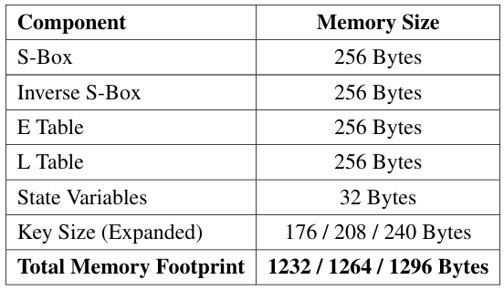 Table 2: Memory Allocation for AES Library
IV.2 ExecutionTiming
Execution time was measured using the internal SysTick timer running at a 16MHz clock frequency.
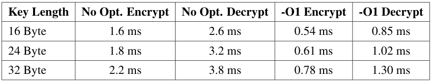 Table 3: Time Taken per 16-Byte Block at 16MHz Clock
As evident, enabling standard compiler optimizations (-O1) reduces execution time by over 60%.
IV.3 Comparative Analysis of Cipher Modes
To encrypt messages longer than 16 bytes, block cipher modes of operation must be utilized.
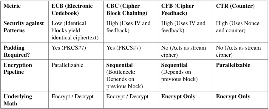 Table 4: Performance and Operational Comparison of AES Modes
PerformanceTake away for TIVA C:CTR mode is theoretically the fastest and most efficient mode for the Tiva C architecture because it acts as a stream cipher (requiring no padding computation overhead) and uses only the AES Encryption function for both encrypting and decrypting. CBC provides robust security but introduces a sequential bottleneck during transmission, as the microcontroller cannot begin encrypting block N until block N −1 is fully computed.
IV.4 Board-to-Board Communication Metrics
The system utilizes UART5 for transmission. Evaluating the performance of the communication channel is critical for embedded applications.
• Baud Rate: 115,200 bits per second (bps).
• Maximum Throughput: 115,200÷10=11,520 bytes/second (≈11.5 KBps).
• Packet Size (Ps): The SecurePacket structure equals 85 Bytes.
• Transmission Latency: The time required to physically transmit one fully loaded secure packet over the wire:
Latency = Ps×Bitsperframe / BaudRate = 85×10 / 115200 ≈7.37milliseconds
Combined with the-O1 encryption time of ≈ 0.54ms per block, the total system latency from the moment the user presses “Enter” to the moment the receiving board finishes receiving the electrical signal is highly efficient at under 10 milliseconds.
V.TESTING AND RESULTS
The images below illustrate the hardware setup and the encrypted output for ’chennaisuperking’. This original hardware implementation was tested and verified using an online encryption website.
In our specific implementation, the user inputs the target mode dynamically via hardware switches. They then input the key size, nonce (if applicable), and plaintext message via the console. The microcontroller processes the padding, encrypts the payload, and outputs the resulting Ciphertext as a Hexadecimal string.
In order to verify the results obtained, we used an online AES encryption/decryption tool (http://aes.online-domain-tools.com/). Because our implementation correctly utilizes
the PKCS#7 padding standard for ECB and CBC modes, the hexadecimal ciphertexts generated natively on the Tiva board matched the online professional tools byte-for-byte.
VI.CONCLUSION
The AES encryption/decryption algorithm was successfully implemented using a highly optimized C library from scratch. By engineering a hardware-driven state machine, we achieve real-time parameterization of key sizes and cipher modes (ECB, CBC, and CTR). Handling strict memory alignments via packed structures and ensuring a robust, non-blocking asynchronous user interface resulted in a high-performance system. With total transmission latencies under 10ms and minimal memory footprint, this project provides a solid, real-world foundation for secure IoT communication using resource-constrained embedded hardware.
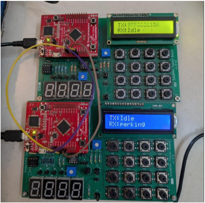 Figure 7: Physical Hardware Setup
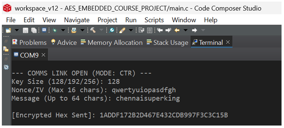 Figure 8: Encrypted message of “chennaisuperking”
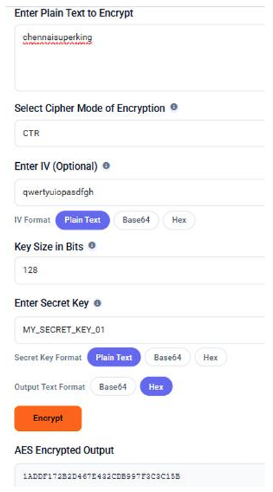
Figure 9: Tested and Verified Encrypted Message
Recent Comments