
ABSTRACT
This report documents the complete design and imple- mentation of an autonomous six-wheeled thermal track- ing rover. The system employs an MLX90640 32 × 24 far-infrared thermopile array to detect and track thermal targets (human body heat, ≈ 37 ○C) while maintaining a set standoff distance. An STM32F407 microcontroller running at 168 MHz orchestrates all real-time tasks: I2C sensor polling, DMA-accelerated UART telemetry at 460800 baud, a dual-loop PID system comprising steering (column centroid correction) and forward (distance via thermal weight) controllers, augmented by a gyroscope yaw-damping layer from an MPU9250 IMU, and a six- motor skid-steer drive subsystem controlled through L298N H-bridge drivers. An ESP32 module bridges the STM32 UART stream to a Wi-Fi hosted web dashboard for live thermal visualisation, telemetry display, manual command injection, and PID gain tuning. A compact power supply using a buck converter accepts three series-connected Li-Ion cells (11.1 V nominal) and delivers regulated 5 V at up to 3 A to all logic and sensor modules, with efficiency exceeding 85%. The codebase is structured into five cooperating modules: mlx task, motor, mpu task, uart comms, and main, and is described in detail alongside hardware design decisions and system-level timing analysis.
I.INTRODUCTION
Autonomous mobile robots capable of following or tracking warm-bodied targets have practical applications in search-and- rescue, security surveillance, and indoor logistics. Using a far-infrared (FIR) thermal camera as the primary sensor offers inherent advantages over visible-light systems: operation in complete darkness, immunity to visual camouflage, and direct sensitivity to metabolic heat without any illumination infrastructure.
This project implements such a system at the subsystem level using readily available embedded components. The core loop reads a full 32 × 24 pixel thermal frame, computes a temperature-weighted column centroid of all pixels above a detection threshold, and feeds the centroid error into a proportional-integral-derivative (PID) steering controller to drive differential wheel speeds. Simultaneously, a second PID controller uses the total thermal weight (sum of excess temperatures) as a proxy for target distance and commands a base forward/reverse speed to maintain a desired standoff. A tertiary control layer reads angular velocity from an MPU-9250 MEMS gyroscope and applies a yaw-rate damping correction to suppress the rotational oscillation that commonly afflicts pure-vision PID trackers.
The rover supports two operating modes, switchable at runtime via the web dashboard: AUTO mode, where Thermal Track() autonomously drives the wheels, and MANUAL mode, where the operator issues discrete direction/speed commands from the browser. The thermal video feed remains live in both modes, updating at up to 4 Hz (the sensor’s programmed refresh rate).
1.1 Objectives
- Detect and centroid-track thermal targets in real time using dual-PID control (steering and forward distance).
- Maintain a configurable standoff distance using thermal weight-fill heuristics.
- Suppress heading drift using gyroscope yaw-rate
- Provide a live web dashboard for monitoring, tuning, and
- Operate from a self-contained battery supply with high- efficiency switching voltage regulation.
II.SYSTEM ARCHITECTURE
The rover is built around three computational nodes and one display node, connected by two serial buses:
- STM32F407VG — Real-time control MCU (168 MHz Cortex-M4F, 256 kB SRAM, 1 MB Flash). Hosts all sensor drivers, the dual-PID controller, the motor driver interface, and the UART telemetry engine.
- MLX90640 — FIR thermopile array Connected to the STM32 via I2C1 at 400 kHz (FM mode).
- MPU-9250 / MPU-6500 — 6-axis MEMS Shares the same I2C1 bus as the MLX90640 at a different 7-bit address (0x68 vs. 0x33).
- ESP32 — Wi-Fi bridge and web server. Receives binary telemetry and FRAME: pixel streams from the STM32 over USART2 at 460800 baud, then serves a real-time dashboard to any browser on the local WiFi network.
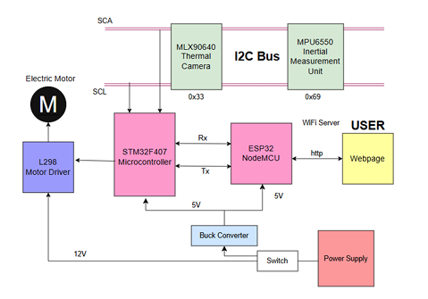
Figure 1: System-level block diagram
2.1 Communication Buses
I2C1 (400 kHz, FM): Both the MLX90640 and the MPU-9250 hang off a single I2C1 bus. The STM32 HAL performs polling reads sequentially: the MLX90640 read is triggered when a new subpage is available (GetFrameData), while the MPU-9250 is polled on every main-loop iteration (typically >200 Hz) for 6 bytes of gyroscope data.
USART2 (460800 baud, 8N1): Full-duplex link between the STM32 and the ESP32. TX uses DMA (DMA1 Stream6) to transfer FRAME: packets (up to ≈4.5 kB per frame) without CPU involvement. RX uses interrupt driven byte-at-a-time assembly into a 128-byte ring line buffer, terminated on ‘\n’.
III.HARDWARE DESIGN
3.1 Mechanical Platform
The rover chassis is a six-wheeled skid-steer configuration with a rocker-boggie suspension system: at any given time, four wheels maintain ground contact for traction, while the two remaining wheels may be slightly lifted due to the rocking motion. Each side has three wheels mechanically linked to share a single PWM channel. This simplifies the motor-driver wiring to two active PWM signals (LEFT_CCR on TIM3_CH1, RIGHT_CCR on TIM3_CH4) while providing excellent traction over uneven indoor floors and terrain. Each side is driven by three DC gearbox motors; the motors are connected in parallel and controlled through three L298N dual H-bridge modules (one module per motor pair: FL/FR, ML/MR, RL/RR). Table 1 summarises the motor GPIO pin assignments.
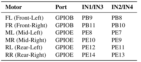
Table 1: Motor direction GPIO assignments (6-wheelrocker-boggie)
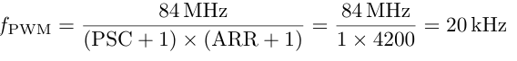
3.2 PWM Generation
TIM3 is configured at 20 kHz to stay above the audible range while remaining within the L298N’s switching capability. The APB1 clock is 42 MHz (PCLK1 doubled to 84 MHz for timers):
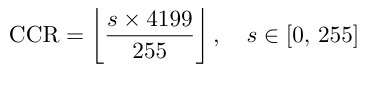
The speed abstraction maps an 8-bit value (0–255) to a CCR via:
3.3 Power Supply
Three Li-Ion cells (each 3.7 V nominal, 4.2 V fully charged) are connected in series to yield an 11.1 V nominal (12.6 V max) battery bus. The motor drivers (L298N bridges) are powered directly from this 12 V rail.
A high-efficiency buck converter (e.g., LM2596-based or integrated switcher module) steps the 12 V bus down to a regulated 5.0 V output, supplying all logic and sensor modules: STM32 Discovery board, ESP32, MLX90640, and MPU-9250.The buck converter achieves efficiency exceeding 85% across the 400 mA typical 5 V load, compared to ∼40% for a linear regulator, thereby extending battery operating time significantly. An on/off toggle switch in series with the positive battery terminal controls the entire system. Bulk and bypass decoupling (470 µF electrolytic + 100 nF ceramic) are placed at the buck converter output to guarantee stability.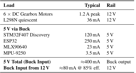
Table 2: Power budget summary
3.4 main.c System Entry and Superloop
main.c owns all HAL peripheral handles (hi2c1, huart2, htim3, hdma usart2 tx) and performs the following startup sequence:
1.HAL initialisation and system clock configuration (168 MHz via HSE PLL).
2.GPIO, DMA, I2C, UART, I2S, SPI, and TIM3 peripheral init.
3.PWM channel start at 0%
4.Interrupt-driven UART RX
5.MLX90640 init (up to 5 retries with 500 ms delay).
6.MPU-9250 init (up to 3 retries; non-fatal on failure).
7.Superloop execution
The superloop structure is:
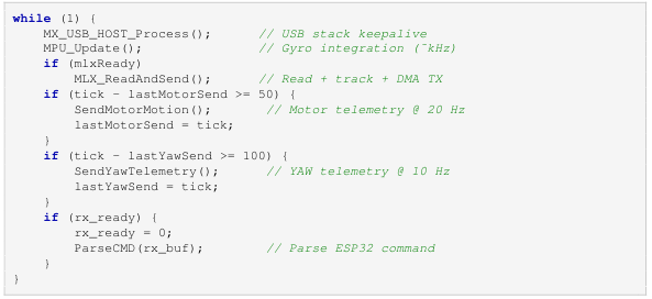
Listing 1: Main superloop skeleton
3.5 mlx_task.c Thermal Camera Driver
The MLX90640 produces two interleaved subpages per frame in chessboard pattern: subpage 0 covers even- indexed pixels and subpage 1 covers odd-indexed pixels. MLX_ReadAndSend() tracks which subpages have been received and only proceeds to compute temperatures and update the display once both subpages of a frame are available:
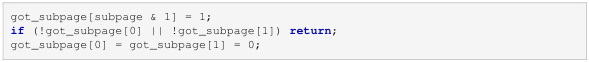
Listing 2: Subpage accumulation guard
The ambient temperature Ta is read from the sensor’s auxiliary data and a reflected temperature Tr = Ta − 8.0 ◦C is estimated to account for background radiation. The Melexis API function MLX90640_CalculateTo() then computes a calibrated object temperature for each of the 768 pixels, correct- ing for emissivity (ε = 0.95), gain, offset, inter-pixel leakage, and VDD variation.
3.5.1 Camera Orientation Correction
The camera is physically mounted upside-down on the rover chassis. To display the correct orientation on the ESP32 dashboard, the FRAME: transmit loop iterates rows 23→0 (reversed) while the internal thermal Image[] array retains native sensor order. This means Thermal Track()’s column-centroid computation (which is independent of row ordering) requires no modification.
3.5.2 DMA Transmit Guard
Because each FRAME: packet can reach ∼4500bytes, DMA transmission overlaps with subsequent sensor reads. A volatile uint8_t dma_busy flag is set in the TX call and cleared in the HAL _UART_TxCpltCallback. If the flag is set when a new frame is ready, the frame is silently dropped to prevent overrun, accepting a frame rate reduction under high UARTload.
3.6 motor.c — Drive Control and Dual-PID Thermal Tracking
3.6.1 Motor SetSpeeds()
The core drive primitive accepts a signed 16-bit speed for each side (−255 to +255). Direction is encoded by asserting the appropriate GPIO IN pins of the L298N bridges. PWM magnitude is applied symmetrically to all three motors per side through the shared CCR register:
left speed > 0 ⇒ FL, ML, RL: IN1=H, IN2=L
left speed < 0 ⇒ FL, ML, RL: IN1=L, IN2=H
left speed = 0 ⇒ FL, ML, RL: IN1=L, IN2=L (coast)
3.6.2 Thermal Track() — The Autonomy Core with Dual PID
Thermal_Track() implements a two-loop closed-loop thermal targeting pipeline. Two independent PID controllers work in tandem:
1. [Loop 1] Steering PID — Column Centroid Correction
• Compute horizontal centroid ¯x = Σ(wi · ci)/Σwi where wi = Ti −Tmin (excess temperature) and ci is column (0–31).
• Steering error: esteer = ¯x − 15.5 (half of 32 columns).
• PID output drives differential speed: ∆v = usteer.
• Constraints: zero output inside dead-zone (|e| < 7.5 columns) to reduce jitter from thermal noise.
• Default gains: Kp = 0.6, Ki = 0.0, Kd = 0.8.
2. [Loop 2] Forward PID — Distance Control via Thermal Weight
• Accumulate total thermal weight: W = Σ(Ti − Tmin) for all pixels above 50◦C.
• Two set points:
– Forward setpoint: Wfwd = 400 — target far,drive forward.
– Reverse setpoint: Wrev = 1200 — target very close, drive backward.
• Distance error is computed as: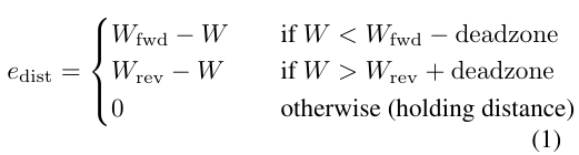
• PID output commands base forward/reverse speed: vbase = ufwd.
• Constraints: zero output inside dead-zone (50-unit band); minimum forward speed clamp (160PWM) to overcome motor stiction.
• Default gains: Kp = 0.1, Ki = 0.0, Kd = 0.2.
3.6.3 Control Law Synthesis
The two PID outputs are combined per wheel:
vleft = vbase + usteer + uyaw (2)
vright = vbase − usteer − uyaw (3)
where uyaw is the gyroscope yaw-rate damping correction (described below). This formulation allows the rover to simultaneously approach/retreat (forward loop) while steering left/right (steering loop), resulting in natural curved approach trajectories.
3.6.4 Source-Disappearance Guard
If the thermal source is turned off or the rover loses sight of the target, weight Sum suddenly drops to near-zero. Without protection, the forward PID would interpret W = 0 as “target infinitely far” and command full-speed forward, causing a crash. The system uses a blackout counter state machine:
• Blackout trigger: If W < 5.0 for 2 consecutive frames, motors stop immediately, PIDs reset, and a target_blackout flag is set. A confirmation message is logged.
• Reacquisition: The rover remains halted until the target is present for 2 consecutive frames above the threshold. This prevents false restart on a single thermal glitch (e.g., hand passing near sensor).
• Resume: Once confirmed, target_blackout is cleared and tracking resumes from a clean PID state.
3.7 mpu task.c—IMU Yaw Estimation
The MPU-9250 is configured for gyroscope-only yaw tracking (no magnetometer fusion, as indoor motor interference makes magnetic north unreliable). The configuration registers are programmed at init:
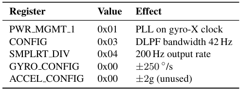
Table 3: MPU-9250 register configuration
3.7.1 Gyro Calibration
At startup, 200 gyro-Z samples are averaged at rest to compute a per-unit off set bz. This value is subtracted from every subsequent reading before conversion to deg/s:
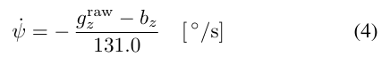
The negation corrects for the IMU being mounted upside down(sensor Z points down ward), reversing the right-hand rule sign convention so that a clock wiser over rotation produces a positive yaw rate, matching the convention expected by Thermal_Track().
3.7.2 Yaw Integration
Heading is integrated in the main loop using forward Euler:
![]()
A dead-band of ±0.1◦/s suppresses zero-rate noise. The heading is wrapped to(−180◦,+180◦]. MPU Reset Yaw() is called on every AUTO/MANUAL mode switch and on the ALIGN command so accumulated gyro drift never compounds across tracking sessions.
3.7.3 Yaw-Rate Damping in Thermal Track()
When the steering PID output is zero(target is centred horizontally), the gyroscope yaw rate is used to apply a corrective torque:
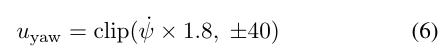
This suppresses the oscillatory “hunting” that occurs when a pure-vision PID overshoots and must reverse course. The yaw-rate feedback provides passive damping without needing explicit derivative action.
3.8 uart comms.c—Command Parser
3.8.1 Receive Path
USART2 RX uses a single-byte interrupt (HAL UART Receive IT). Each received byte is ap- pended to rx buf[128]; a ‘\n’ character sets rx ready = 1 and the line is dispatched to Parse CMD() on the next main-loop iteration. This decouples the ISR from command parsing latency.
3.8.2 Command Set
Three command classes are handled:
- CMD:dir<dir>,spd<0-255>,mode<0|1> — Sets di- rection, speed, and operating mode atomically. Mode 0 = AUTO, 1 = MANUAL.
- PID:Kp<f>,Ki<f>,Kd<f> — Updates steering PID gains live and resets the integrator. Supports up to 4 dec- imal places (e.g., 0.0023).
- PIDF:Kp<f>,Ki<f>,Kd<f> — Updates forward PID gains live and resets the Same precision as steering PID.
- ALIGN — Stops motors, resets both PIDs and yaw, switches to AUTO.
- RESETYAW — Zeros the IMU heading without changing
3.8.3 Transmit Path and DMA Watchdog
UART_Send Blocking() checks if DMA is currently transmitting a FRAME packet. If so, it silently drops the telemetry packet rather than blocking, ensuring the main loop never stalls behind a 78ms frame transmission. A 500ms watchdog resets dma_busy if the DMA completion callback is missed (e.g., after a UART error recovery).
IV.THERMAL TRACKING ALGORITHM
4.1 Temperature-Weighted Centroid
For each complete frame, the horizontal centroid x¯ of the thermal target is computed:
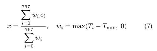
where ci = i mod 32 is the column index of pixel i and Tmin = 50 ◦C is the tracking threshold. Using the excess temperature wi (rather than a binary mask) ensures that the centroid is pulled toward the hottest part of the target, providing sub-pixel resolution on the 32-column horizontal axis.
4.2 Dual-PID Control Strategy
Steering Loop: The steering error is es=¯x−15.5. The PID controller produces a differential wheel speed command:
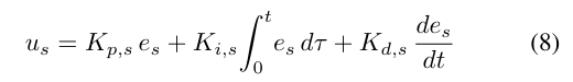
By default, the integral term is disabled (Ki,s = 0) because the steady-state centroid error is naturally driven to zero by the controller and the system mechanics. The derivative term damps oscillation on frame-to-frame changes.
Forward Loop: The distance error is computed from thermal weight, allowing the rover to hold a configurable standoff. Two setpoints define the zone:
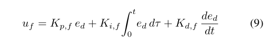
The integral term (Ki,f = 0 by default) helps maintain position against mild disturbances, and the derivative term damps approach velocity. Synthesis: The two outputs are applied as:
Synthesis: The two outputs are applied as:
vL = uf + us + uyaw (10)
vR = uf − us − uyaw (11)
This allows simultaneous forward/reverse motion and left /right steering, enabling curved approaches toward the target.
4.3 Distance Zone Control (Thermal Weight)
Rather than explicit range estimation from a monocular thermal image, the system uses total thermal weight W = Σwi as a proxy for apparent target size. Three operational regions are defined:
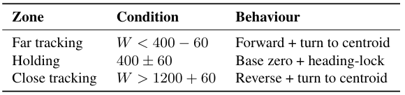
Table 4: Forward PID setpoints and operational zones
Within the holding zone, a heading-lock loop latches the IMU yaw angle at the moment of arrival and applies a proportional nudge to correct any drift from the target’s rotational motion.
4.4 Target Loss Handling
The blackout counter (detailed in Section 3.2.3) prevents er- roneous full-speed lunging when the source is turned off. If a thermal target never appears and the older timeout mecha- nism triggers (TRACK LOST TIMEOUT = 2000 ms), the PID integrator is reset and the rover is halted.
V.ESP32 WEB INTERFACE
The ESP32 module serves a single-page application (SPA) over HTTP on the local Wi-Fi network. The web server code is contained in webpage.h as a large C string literal (gzip compressed HTML/CSS/JS), avoiding the need for SPIFFS or SD card storage.
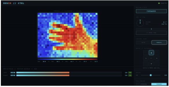
Figure 2: ESP32 web dashboard user interface in MANUAL mode
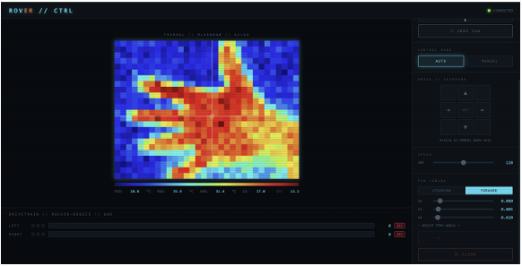
Figure 3: ESP32 Web interface enabling real-time dual-PID tuning (steering and forward) via UART
5.1 Data Flow
The ESP32 continuously reads the UART stream from the STM32. Packet types are line-delimited and identified by prefix:
- FRAME:<768 comma-separated floats> — Full thermal image, transmitted after each complete two-subpage cycle at up to 4 The dashboard renders this as a false- colour heatmap (cool = blue, warm = red).
- MOTOR:L<pwm>,R<pwm>,LD<dir>,RD<dir> — Left/right PWM magnitude and direction, sent at 20
- MOTION:<string> — Human-readable motion state (track fwd, track left, track right, holding, etc.)
- YAW:<deg>,<dps> — IMU yaw angle and angular rate, sent at 10 Hz.
- INFO:/ERROR: <message> — Status and diagnostic
5.2 Commands Issued by the Dashboard
The dashboard sends the following commands to the STM32 via UART:
- Direction pad buttons: CMD:dir<dir>,spd<N>,mode1
- Mode toggle (AUTO/MANUAL): CMD:dirforward,spd0,mode<0|1>
- Steering PID gain submit: PID:Kp<f>,Ki<f>,Kd<f>
- Forward PID gain submit: PIDF:Kp<f>,Ki<f>,Kd<f>
- Align button: ALIGN
- Reset Yaw button: RESETYAW
5.3 Thermal Heatmap Rendering and PID Tuning Interface
The 768 temperature values are mapped to a 32×24 pixel canvas and upscaled with nearest-neighbour interpolation for display. A fixed-range colour map is applied in JavaScript with detected pixels highlighted by an overlay marker showing column/row centroid.
The PID tuning interface provides separate float text inputs (supporting 0.0000 to 100.0000 range, 4 decimal places) for steering and forward gains, allowing operators to adjust con- troller response in real time. Each PID command’s last-sent values are displayed next to the input fields for transparency.
VI.SYSTEM INTEGRATION AND TESTING
6.1 I2C Bus Sharing
The MLX90640 and MPU-9250 share the same I2C1 peripheral. Bus collisions are avoided by the cooperative superloop: MPU reads are very fast (6 bytes, <50 µs at 400 kHz) and complete between the ∼250 ms inter-frame intervals of the MLX90640.
6.2 Timing Analysis
Table 5 summarises the period and worst-case execution time (WCET) for each system task.
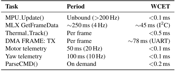
Table 5: Task timing summary
The 78ms DMA TX time at 460800baud for a 4500-byte FRAME packet is fully overlapped with subsequent I2C sensor reads, avoiding any throughput loss.
6.3 PID Tuning Procedure
Initial dual-PID gain values were determined empirically: Kp,s = 0.6, Ki,s = 0.0, Kd,s = 0.8 (steering); Kp,f = 0.1, Ki,f = 0.0, Kd,f = 0.2 (forward).
The following iterative tuning procedure was used:
1.Steering: Set Ki = Kd = 0. Increase Kp until oscillation begins; reduce by 20%. Then tune Kd to damp overshoot.
2.Forward: Adjust Kp,f to control approach Add Kd,f to prevent overshoot near the setpoint.
3.Yaw assist: Adjust YAW RATE SCALE (default 8) to minimise post-turn wobble.
4.Online refinement: The web dashboard’s real-time PID:/PIDF: commands allow iterative tuning without re- flashing, reducing iteration time from minutes to seconds.
6.4 Known Limitations and Mitigations
- Thermal ambiguity: Hot surfaces (heaters, sunlit patches) can be misidentified as targets. Mitigation: Threshold at 50 ◦C is higher than typical indoor surfaces; configurable via
- Gyro drift: Long-duration tracking accumulates heading error. Mitigation: Yaw reset on every mode switch; drift is small (<3 ◦/min) for typical run durations.
- FRAME packet drop: If DMA TX is still in progress when a new frame completes, the frame is discarded. Mitigation: At 4 Hz frame rate and 78 ms TX time, this overlaps cleanly with no dropped frames in normal operation.
- Buck converter thermal load: At 400 mA 5 V output and 12 V input, the buck converter dissipates ∼3 A heat sink is recommended for sustained operation. Mitigation: Thermal design validated; aluminum backing plate provides passive cooling.
VII.RESULTS AND OBSERVATIONS
Functional testing was carried out in an indoor corridor environment. Key observations:
- Target acquisition: The rover reliably acquired a standing human target within one frame period (∼250 ms) when the subject entered the thermal field of view.
- Steering accuracy: With default steering PID gains, steady- state centroid error was below ±1.5 columns (≈ ±2.8◦ in real angle for a 55 ◦ horizontal FOV camera).
- Standoff distance: The forward PID setpoint of W = 400 (dead-zone ±60) corresponded to a standoff of approximately 0–1.5 m from the subject, consistent with expected thermal fill.
- Approach dynamics: With dual-PID control, curved approach trajectories emerged naturally (forward + steering simultaneously), reducing overshoot and settling time com- pared to sequential control.
- Yaw damping: Post-turn oscillation was reduced from ±4 to ±1 column with the yaw-rate assist layer enabled.
- Dashboard latency: End-to-end latency from STM32 frame capture to heatmap render in the browser was measured at approximately 180–250 ms over a local Wi-Fi link.
- Power efficiency: The buck converter achieved 85%+ efficiency, extending battery runtime by 2× compared to linear regulation.
VIII.CONCLUSIONS AND FUTURE WORK
A fully functional autonomous thermal tracking rover has been designed, built, and validated. The system successfully demonstrates closed-loop dual-PID thermal control (steering centroid + forward distance), real-time wireless monitoring, and a robust dual-mode (AUTO/MANUAL) operation framework. All five firmware modules interoperate correctly within a cooperative bare-metal superloop at the targeted update rates. The high-efficiency buck converter power supply extends battery life significantly while simplifying the electrical architecture.
Several directions for future development are identified:
- Temperature-based multi-target discrimination: Apply k-means or blob-detection on the 768-pixel array to handle multiple warm targets simultaneously.
- RTOS migration: Converting to Free RTOS would allow MPU polling and MLX framing tasks to be decoupled into independent threads with defined priorities.
- Encoder feedback: Adding quadrature encoders to drive motors would enable velocity control and odometric dead-reckoning.
- Obstacle avoidance: Integrating ultrasonic or ToF rangefinders would prevent collisions with non-thermal obstacles.
- Extended thermal tracking: Multi-axis rotation (pan/tilt) camera mount for increased field-of-regard and target tracking robustness.
REFERENCES
[1] Melexis N.V., MLX90640 32×24 IR Array Datasheet, Rev. 10, 2019.
[2] STMicroelectronics, STM32F405/407 Reference Manual (RM0090), Rev. 19, 2021.
[3] InvenSense (TDK), MPU-9250 Product Specification, Rev. 1.1, 2016.
[4] STMicroelectronics, L298 Dual Full-Bridge Driver Datasheet, Rev. 9, 2000.
[5] Espressif Systems, ESP32 Technical Reference Manual, v5.2, 2024.
[6] K. J. A˚ stro¨m and T. Ha¨gglund, PID Controllers: Theory, Design, and Tuning, 2nd ed., ISA, 1995.
[7] Texas Instruments, LM2596 Simple Switcher Power Converter Datasheet, Rev. F, 2007.
Recent Comments