
ABSTRACT
This project presents the design and implementation of an audio fol- lower robot using the Time Difference of Arrival (TDOA) concept. The system utilizes two MAX4466 electret microphone amplifiers to capture sound signals and determine the direction of the sound source based on the time delay between them. A TM4C123GH6PM Tiva C Series microcontroller processes the acquired signals and calculates the relative arrival time to estimate the direction. Based on this information, appropriate control signals are generated for the L298N motor driver module to drive the robot toward the sound source. The system is powered using two 3.7V Li-ion batteries connected in series. The proposed design demonstrates a simple and effective method for real-time sound localization and autonomous navigation, making it suitable for applications in surveillance, human-following robots, and assistive robotics.
I.INTRODUCTION
Sound-based navigation is an important aspect of autonomous robotics, enabling systems to interact with their environment without relying on visual inputs. In recent years, audio- guided robots have gained attention for applications such as surveillance, search and rescue, and human-following systems. Unlike vision-based methods, sound localization can operate effectively even in low-light or visually obstructed environments. This project focuses on the development of an audio follower robot using the Time Difference of Arrival (TDOA) technique. The system determines the direction of a sound source by measuring the difference in arrival time of the same sound at two spatially separated microphones. By analyzing this time delay, the robot can estimate whether the sound is coming from the left, right, or front. A TM4C123GH6PM Tiva C Series microcontroller is used to process the audio signals captured by MAX4466 microphone amplifiers. Based on the computed direction, the robot is controlled using an L298N motor driver to move toward the sound source. This approach provides a simple, cost-effective, and real-time solution for sound-based navigation in embedded systems.
II.WORKING PRINCIPLE
The system operates on the Time Difference of Arrival (TDOA) principle using two microphones to detect the direction and angle of an incoming sound signal.
Audio signals from both microphones are sampled simultaneously using ADCs triggered by a timer at a fixed sampling rate. A buffer of samples is collected for each channel and pro- cessed once full. First, the mean is removed from both signals to eliminate DC offset. The system then checks for the presence of a valid sound signal by calculating its energy. If sufficient signal energy is detected, cross-correlation is performed between the two microphone signals over a limited lag range to determine the time delay (lag) between them. Based on the computed lag, the direction is classified as left, right, or cen- ter. The corresponding angle of arrival is calculated using the relationship between lag, microphone spacing, sampling frequency, and speed of sound.
To improve accuracy and avoid noise-based errors, the sys- tem repeats this process for 10 consecutive frames and uses a majority decision to determine the final direction. Once a consistent direction is identified, the robot rotates toward that direction.
After rotation, the system checks whether the sound source is aligned at the center. If not, the sensing process repeats. When the sound is detected at the center, the robot moves for- ward for a fixed duration of 450 ms. This cycle continues, enabling continuous tracking of the sound source.
III.SYSTEM ARCHITECTURE
The system consists of the following functional blocks:
- Acoustic Sensing Unit : Two microphones capture sound
- Data Acquisition Unit : Timer-triggered ADC
- Signal Processing Unit : Cross-correlation and delay estimation
- Decision Logic : Direction validation using majority filtering
- Control Unit : Motor direction and PWM speed
- Actuation Unit : Differential drive
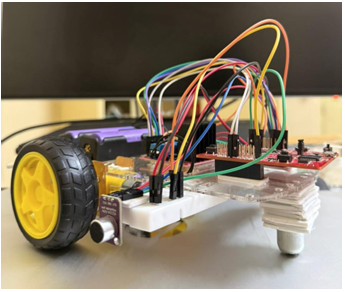
Figure 1: Audio Follower Bot
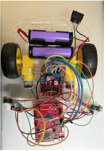
Figure 2: Audio Follower Bot(Top View)
IV.HARDWARE DESCRIPTION
4.1 Microcontroller
The TM4C123GH6PM is used due to:
- Dual ADC modules (parallel sampling)
- Hardware timers for precise sampling
- PWM modules for motor control
- Interrupt-based processing
4.2 Microphones (MAX4466)
- Provide amplified analog audio signals
- Connected to ADC channels PE2 and PE3
4.3 Motor Driver (L298N)
- Controls direction and speed of motors
- Uses PWM (enable pins) and GPIO (direction pins)
4.4 Power Supply
- Two Li-ion cells (7.4V nominal)
- Supplies both logic and motor circuitry
V.SOFTWARE ARCHITECTURE (STATE MACHINE BASED DESIGN)
The system is implemented using a finite state machine (FSM) approach, where the robot transitions between well-defined states based on sensor input and decision logic. This ensures structured execution, reduces instability, and improves robustness in noisy environments.
5.1 Listening State (Sensing + Processing)
What Happens in this state is :
- ADC sampling is started using timer
- A frame of 500 samples is collected from both micro-
- Signal processing steps are applied:
- DC offset removal
- Energy detection (to ignore silence/noise)
- Cross-correlation to find lag
- Direction and angle estimation
5.2 Decision Logic
- The system does not act
- It waits for consistent detection:Same direction must re- peat 10 times (MATCH-COUNT).
- If direction changes : counter
- If no valid signal : ignored (fast retry). Why this state is important:
- Prevents false triggering due to noise
- Ensures only reliable direction is used
5.3 Acting State (Control + Movement)
This state is entered when a stable direction is detected (10 matches),What happens here:
- ADC sampling is stopped (to avoid interference)
- Based on detected direction:
- Case 1: CENTER:
- Robot moves forward
- Includes: Small reverse (to align wheels),Then for- ward motion.
- Case 2: LEFT or RIGHT
- Robot rotates in that direction
- Speed (PWM duty) depends on angle:
- Larger angle : higher speed
- Small angle ignored
5.4 Settling State (Stabilization Phase)
After motion is completed, what happens here is:
- System waits for 1 second (SETTLE TIME MS)
- No sensing or movement during this time
- It eliminates: Mechanical vibrations, Residual motion noise, False audio readings caused by motors Without this state : system becomes unstable and oscillatory
5.5 State Transition Flow
Listening →(10 consistent detections) → Acting → Settling→ Listening Again
VI.SIGNAL ACQUISITION
- Sampling frequency: 25 kHz
- Number of samples per frame: 500
- Timer-triggered ADC ensures synchronized sampling ( fs = 25 kHz, N = 500). This provides sufficient temporal resolution for detecting microsecond-level delays.
VII.SIGNAL PROCESSING
7.1 DC Offset Removal
Each signal is mean-centered: x[n] = x[n] −µ
7.2 Signal Detection
Energy-based thresholding:
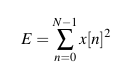
If E < threshold, it is ignored (noise rejection).
7.3 Cross-Correlation (Core of TDOA)
Cross-correlation:
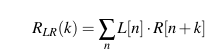
Lag range: −20 to +20 samples.
Maximum correlation → best lag ,where k is lag
7.4 Direction Estimation
- If k > 1 → Right
- If k < −1 → Left
- Otherwise → Center
7.5 Angle Estimation
![]()
Where:
7.6 Decision Logic
To avoid noise-based false decisions:
- System processes multiple frames
- Requires 10 consecutive matches of direction
- Uses majority + consistency logic
Key Features:
- Ignores silence frames
- Resets on mismatch
- Uses running average for angle This significantly improves
7.7 Motor Control
7.7.1 Direction Control
GPIO pins control motor direction(High pin):
- LEFT (Blue LED) → PB1 + PB4
- RIGHT (Red LED) → PB0 + PB5
- FORWARD (Green LED)→ PB0 + PB4
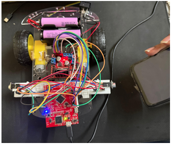
Figure 3: Bots Left Direction is Detected
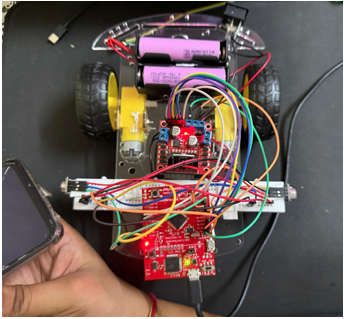
Figure 4: Bots Right Direction is Detected
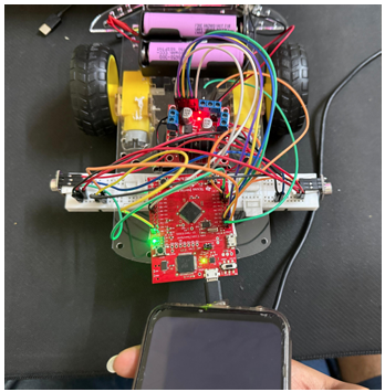
Figure 5: Bots Center Direction is Detected
7.7.2 PWM Control
• PWM frequency: 1 kHz
• Duty cycle controls speed:
7.7.3 Rotation Strategy
Angle mapped to PWM duty:
duty ∝ |θ |
- Small angles ignored (< 4.5◦)
- Fixed rotation duration: 90 ms
7.7.4 Forward Motion Strategy
Includes:
- Forward motion (450 ms)
This improves trajectory stability.
7.7.5 Halting
For halting the bot to avoid collision with the sound source, we are using energy as threshold. When the bot is too close to the sound source the energy received is massive, which we have set a threshold. If centre is received and energy is above threshold, then bot will stop there only. And also to insicate halting, white LED will Glow.
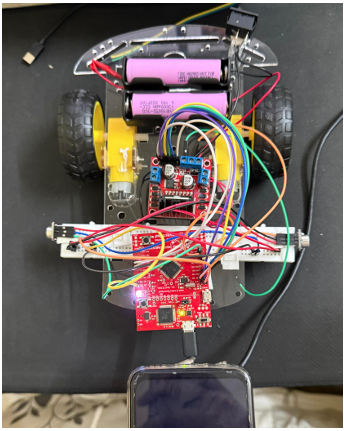
Figure 6: Halting, Sound source is close
7.8 State Machine Operation
7.8.1 Listening
- Acquire signal
- Process direction
- Check consistency
7.8.2 Acting
- Rotate → adjust orientation
- Move forward
7.8.3 Settling
- Wait 1 s
- Avoid oscillations
VIII.KEY DESIGN CONSIDERATIONS
- Sampling synchronization is critical for TDOA accuracy
- Limited lag window reduces computation
- Energy thresholding removes noise
- Majority voting improves reliability
- PWM scaling ensures proportional control
IX.RESULTS
- Accurate direction detection (Left/Right/Center)
- Ignoring the signals which gives energy below certain threshold energy, it denotes silence and displays ”Silence” on the terminal.
- Stable tracking after multiple confirmations
- Smooth motion using PWM control
- Robust against noise due to filtering logic
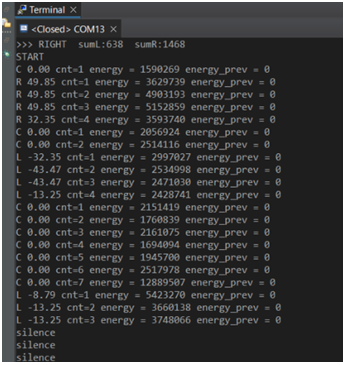
Figure 7: Terminal-: Values Detected
X.CONCLUSION
The project successfully demonstrates a real-time embedded implementation of an audio-following robot using the TDOA principle. The combination of signal processing, decision filtering, and motor control results in a robust and efficient system capable of tracking sound sources. The design highlights practical challenges in embedded robotics and provides a scalable foundation for advanced acoustic navigation systems.
REFERENCES
- Tiva™ TM4C123GH6PM Microcontroller DATA SHEET https://www.ti.com/lit/ds/symlink/tm4c123gh6pm.pdf
- Tiva™ C Series TM4C123G Launch- Pad Evaluation Board User’s Guide https://www.ti.com/lit/ug/spmu296/spmu296.pdf?ts=1769282922 431&ref url=https%253A%252F%252Fwww.google.com%252F
- https://labs.dese.iisc.ac.in/embeddedlab/pwm/
- https://labs.dese.iisc.ac.in/embeddedlab/adc-devices/
Recent Comments