
ABSTRACT
This project presents the design and implementation of a portable smart navigation and location-sharing system based on the TM4C123GH6PM microcontroller. The system integrates a Global Positioning System (GPS) receiver, an inertial measurement unit (IMU), a digital magnetometer, an OLED display, addressable LED indicators, and LoRa wireless communication to provide real-time navigation and long-range location sharing. Sensor fusion using accelerometer, gyroscope, and magnetometer measurements enables robust heading estimation, while GPS coordinates are used to calculate bearing and distance to selected destinations. A localization engine provides continuous position estimation during GPS outages, and a lightweight custom LoRa protocol allows multiple devices to exchange live location information over long distances. Experimental results demonstrate accurate heading estimation, reliable wireless communication, and intuitive visual navigation, highlighting the suitability of embedded sensor fusion and wireless localization systems for outdoor navigation applications.
I.INTRODUCTION
Embedded navigation systems have become increasingly important in applications such as outdoor tracking, rescue operations, autonomous guidance, and collaborative positioning. Conventional smartphone-based navigation systems rely heavily on internet connectivity and high-power processing, limiting their use in remote environments.
Microcontroller-based navigation systems provide an efficient alternative due to their low power consumption, real-time performance, and independence from network infrastructure. By integrating GPS positioning, inertial sensing, and wire-less communication, reliable navigation can be achieved using compact embedded hardware.
This system is designed to operate as one of two symmetric peer devices, referred to as Holder 1 and Holder 2. Each device is identically configured in hardware and firmware, differing only in a compile-time identity parameter that assigns its LoRa address and peer reference. This symmetric architecture ensures that either device may initiate communication and that the roles of sender and requester are fully interchangeable.
II.MOTIVATION
The motivation behind this project stems from the growing demand for portable navigation systems capable of operating independently of cellular or internet infrastructure. In many out-door environments such as campuses, trekking routes, disaster zones, and remote research sites, reliable location sharing and directional guidance are critical.
This project provides hands-on experience in embedded system design, sensor interfacing, real-time data processing, wireless communication, and sensor fusion. It also demonstrates how multiple sensing modalities can be integrated to build a practical navigation system on a resource-constrained microcontroller platform.
III.BACKGROUND STUDY
3.1 Global Positioning System (GPS)
GPS provides real-time geographical coordinates by receiving signals from multiple satellites. The GPS module continu-ously transmits NMEA sentences containing latitude, longi-tude, time, and validity information.
In this project, the $GPGLL sentence is used to extract loca-tion coordinates. The received coordinates are converted into decimal degrees before further processing.
The great-circle distance between two coordinates is calculated using the Haversine formula:
where:
- R is the Earth radius
- φ is latitude
- λ is longitude
The bearing angle toward the destination is computed as:
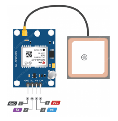
Figure 1: NEO-6M GPS module
3.2 Inertial Measurement Unit (IMU)
The MPU6050 combines a 3-axis accelerometer and a 3-axis gyroscope to measure device orientation and rotational motion.
The accelerometer estimates roll and pitch:
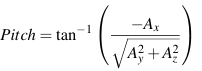
The gyroscope measures angular velocity, enabling dynamic heading tracking.
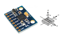
Figure 2: MPU 6050 IMU sensor
3.3 Digital Magnetometer
The QMC5883P magnetometer measures the Earth’s magnetic field along three axes, enabling compass functionality.
Tilt compensation is performed using roll and pitch estimates:
Xh = Mx cos(Pitch) + Mz sin(Pitch)
Yh = Mx sin(Roll) sin(Pitch)+My cos(Roll)−Mz sin(Roll) cos(Pitch)
The magnetic heading is then calculated as:
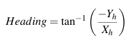
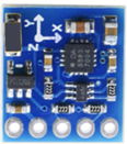
Figure 3: QMC 5883 Magnetometer
3.4 Complementary Sensor Fusion
To improve heading stability, gyroscope and magnetometer measurements are combined using a complementary filter:
θf = αθg + (1 −α)θm
where:
• θf = fused heading
• θg = gyroscope heading
• θm = magnetometer heading
• α = 0.95
3.5 Localization
Localization is a method of estimating the current position of a device based on a previously known position, updated using motion measurements over time. When GPS signal is temporarily unavailable, the system continues to estimate position by integrating step-counted displacement along the last known heading.
The technique relies on a pedestrian step detection model. Detected steps are projected onto the north and east axes using the fused compass heading and the bearing toward the current navigation target. This allows the system to continue updating distance and bearing estimates even in the absence of satellite fixes.
Error accumulates over time due to heading uncertainty and fixed step-length assumptions. A maximum drift threshold is defined beyond which the system raises a visual warning to the user, indicating that the localization estimate may no longer be reliable.
3.6 Step Detection
Step detection in pedestrian localization is typically performed by analysing the periodic oscillations in the total acceleration magnitude produced by the gait cycle. A common approach is a peak-valley state machine, in which a step is counted only upon completion of a full acceleration oscillation that is when the magnitude rises above an upper threshold (peak) and subsequently falls below a lower threshold (valley).
This two-threshold hysteresis design prevents spurious step counts caused by vibration or partial oscillations. A minimum inter-step interval is also enforced so that rapid noise transients cannot generate unrealistic step rates.
Upon each confirmed step, the displacement is projected onto the absolute north and east axes using the current fused compass heading and the bearing from the current position to the selected navigation target. The projection model assumes that the user is walking in the general direction indicated by the compass, allowing the north and east offsets to be updated as:
∆N = −ds · cos(θhdg −θbrg) · cos(θbrg)
∆E = −ds · cos(θhdg −θbrg) · sin(θbrg)
where ds is the fixed step length, θhdg is the fused heading, and θbrg is the bearing to the current target. The sign convention is such that a step taken directly toward the target reduces the estimated distance.
The accumulated north and east offsets are converted back to latitude and longitude increments using small-angle approx-imations, and the haversine formula is then applied to recom-pute distance and bearing to any selected target.
A total drift magnitude is maintained, and if it exceeds the configured maximum, a drift warning is shown on the OLED display.
- Chosen upper threshold = 15g
- Chosen lower threshold = 9g
- Chosen Stride length = 7m
3.7 LoRa Communication
LoRa provides long-range, low-power wireless communication suitable for outdoor tracking.
A lightweight ASCII communication protocol is implemented:
- Send location: LOC:<lat>,<lon>
- Request location: REQ:LOC
This enables multiple devices to share coordinates without requiring internet connectivity.
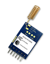
Figure 4: Reyax LORA module
IV.TARGET HARDWARE PLATFORM
The system is implemented on the Texas Instruments TM4C123GH6PM microcontroller operating at 16 MHz.
The hardware configuration includes:
- GPS Module (UART1)
- OLED Display (I2C1)
- MPU6050 IMU (I2C2)
- QMC5883P Magnetometer (I2C0)
- LoRa Module (UART4)
- WS2812B LED Ring (SSI0)
Push Buttons and RGB Indicators
V.DESIGN STRATEGIES
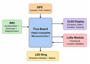
Figure 5: System Architecture
5.1 Interrupt-Based UART Communication
Both GPS and LoRa modules continuously transmit asyn-chronous data. To avoid processor stalls, interrupt-driven ring buffers are implemented for UART reception.
Each UART peripheral is configured to trigger a receive interrupt upon arrival of one or more bytes. The interrupt service routine transfers incoming bytes directly into a circular ring buffer, decoupling reception from processing. The main loop drains these buffers at its own rate, ensuring that no in-coming byte is lost even if the processor is busy with sensor computations or display updates.
This allows real-time background data acquisition while maintaining deterministic sensor processing.
5.2 NMEA Sentence Parsing
The GPS module outputs a continuous stream of NMEA-0183 sentences. The system filters specifically for $GPGLL sentences, which carry latitude, longitude, and fix validity. A lightweight byte-by-byte state machine identifies the sentence header and accumulates the payload until the terminating new-line character is received.
Upon receiving a complete and valid sentence, the latitude and longitude fields are extracted, converted from the NMEA degree-minute format into decimal degrees, and stored as the current position fix. A timestamp is recorded at the moment of each valid fix to support GPS timeout detection.
5.3 Localization Mode
The user can explicitly force the device into Localization mode by means of a long-press on the navigation button. This manual mode is intended for situations where GPS may not be available but the user wishes to operate with a fixed base position for example, when navigating indoors or in environments with poor satellite geometry.
When localization mode is engaged, the current GPS coordinates are captured as the base position and GPS updates are suppressed. The mode is indicated on the OLED display and by a distinctive LED blink pattern. A second long-press re-turns the device to normal GPS-based operation.
5.4 Real-Time Sensor Fusion
Sensor measurements are acquired continuously through I2C interfaces. Accelerometer, gyroscope, and magnetometer data are fused in real time using a complementary filter.
The gyroscope angular rate is integrated to produce a short-term heading estimate. Because the gyroscope is subject to slow bias drift, its output is blended with the tilt-compensated magnetometer heading using the complementary filter. The high coefficient α = 0.95 assigned to the gyroscope path sup-presses rapid magnetic disturbances while the small magnetometer term continuously corrects accumulated drift.
Before the main loop begins, the gyroscope Z-axis bias is estimated by averaging a large number of static readings. This calibration offset is subtracted from every subsequent gyro-scope measurement, substantially reducing long-term heading drift.
Tilt compensation of the magnetometer reading uses the roll and pitch angles derived from the accelerometer, projecting the raw three-axis magnetic field measurements onto the horizontal plane before computing the heading. This ensures that the compass heading remains accurate when the device is tilted.
This provides stable heading estimation even under motion and temporary magnetic disturbances.
5.5 Tilt Detection and Display Mode Switching
The system continuously monitors the roll and pitch angles de-rived from accelerometer data to determine whether the device is being held approximately horizontal. A hysteresis scheme with separate enter and exit thresholds prevents rapid flick-ering between display modes when the device is near the tilt boundary.
When the device is tilted beyond the entry threshold, the LED ring switches from compass-navigation mode to a North indicator mode: a single dim white LED marks geographic north relative to the device orientation, while all other LEDs are extinguished. This provides a simple compass reference even when the full navigation display is not appropriate.
When the device returns within the exit threshold, the full navigation display is restored.
5.6 Visual Navigation Interface
A 16-LED WS2812B ring provides intuitive directional guidance. The ring is driven over a synchronous serial interface using a bit-banged protocol that encodes each colour byte as a sequence of high- and low-period SPI pulses matching the WS2812B timing specification.
The North indicator LED is displayed in dim white and its position on the ring is computed from the fused heading, map-ping the heading angle to one of 16 equally spaced sectors centred on the 22.5◦ boundaries. The target direction LED is positioned similarly based on the relative bearing from the current position to the selected destination, and its colour encodes the estimated distance using the following scheme:
- Green: Target within 500 m
- Yellow–Green: 500 m to 1 km
- Orange–Red: 1 km to 3 km
- Deep Red: Beyond 3 km
When both the North indicator and the target indicator fall on the same LED position, a combined colour is displayed that preserves the target colour with an added blue component, en-suring both directions remain distinguishable.
Distance and direction are simultaneously displayed on the OLED screen.
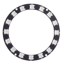
Figure 6: 16-LED ring
5.7 OLED Display Management
The OLED display is driven over I2C using a page-addressed memory model. Custom 5×8 pixel bitmaps are defined for all alphanumeric characters and punctuation required by the interface, avoiding the need for an external font library.
The display is organised into labelled rows carrying the following information: the device identity and selected destination name, the estimated distance to the target, the compass direction sector, and the current operating mode. The mode row indicates one of four states: GPS (normal satellite fix), MANUAL DR (user-forced localization), or NO FIX (awaiting first satellite fix).
To limit I2C bus occupancy during localization location up-dates, the display is refreshed only on every fourth main-loop iteration. Peer location update notifications and request reminders are displayed on a dedicated status row and automatically cleared after a short interval.
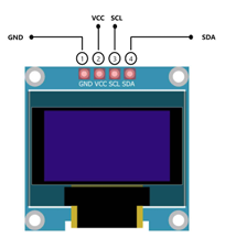
Figure 7: OLED display
5.8 Location Table and Target Selection
The system maintains a static table of named navigation targets, each associated with a latitude, longitude, and a flag indicating whether the entry represents a remote peer device. Fixed infrastructure targets such as campus buildings are pre-loaded with known coordinates. The peer device entry is initially unpopulated and is updated dynamically when a location message is received over LoRa.
The user cycles through the location table using a short press of the navigation button, wrapping around after the last entry. The selected target governs all bearing, distance, and LoRa address computations.
5.9 Location Sharing Protocol
The LoRa communication layer supports three interaction types:
- Location transmission: The device encodes its current position (GPS or localization location estimate) as a decimal latitude–longitude pair in a LOC:<lat>,<lon> payload and transmits it to the peer address using the AT+SEND
- Location request: A REQ:LOC payload is transmitted to the peer to solicit its current coordinates. A pending-request flag is set and a periodic reminder is displayed on the OLED until the peer responds or the user clears the
- Reception and table update: Incoming +RCV= frames from the LoRa module are parsed to extract the sender address and If a LOC: payload is received from a known peer address, the corresponding entry in the lo-cation table is updated and bearing and distance are im-mediately recomputed if that peer is the currently selected target. A REQ:LOC payload sets a request-pending flag and triggers a notification blink pattern.
When in localization mode, the transmitted coordinates reflect the current location estimate rather than the last GPS fix, ensuring that the peer receives the most up-to-date position.
5.10 User Input Handling
Two push buttons are provided. Both are handled by software polling using an accumulated hold-time scheme that distin-guishes short presses from long presses.
SW2 (Navigation button) — A short press cycles the se-lected location target in the destination table. A long press (held for more than one second) toggles localization mode on or off, capturing the current position as the current location base upon activation.
SW1 (Communication button) — A short press transmits the device’s current location to the selected peer over LoRa. A long press sends a location request to the peer. Both actions are blocked with an error indication if the selected target is a fixed infrastructure location (rather than a peer device) or if no position fix is available.
Distinct LED blink patterns and OLED status messages pro-vide unambiguous feedback for each user action and incoming communication event.
VI.IMPLEMENTATION CHALLENGES
6.1 Sensor Synchronization
GPS, IMU, and magnetometer sensors operate at different update rates. Synchronizing these measurements while maintaining real-time performance was a major challenge.
Interrupt-driven communication and periodic sensor polling were used to achieve consistent updates.
6.2 Magnetic Disturbance Compensation
Raw magnetometer readings are sensitive to environmental interference and device tilt. Tilt compensation and complementary filtering significantly improved heading stability.
6.3 UART Buffer Management
Continuous GPS and LoRa data streams can overflow buffers if not processed efficiently.
Ring-buffer-based interrupt handling was implemented to prevent data loss.
6.4 Localization Accuracy
Pedestrian localization is inherently subject to accumulating position error. The primary sources of error in this system are heading uncertainty from the compass and the use of a fixed step length that does not account for individual stride variation. Heading error is mitigated by the complementary filter and gyroscope bias calibration, but residual magnetic disturbances remain a limiting factor. Step-length variation is addressed by using a conservative fixed estimate and by implementing a drift warning that alerts the user when accumulated displacement exceeds a safe threshold. Users are expected to re-anchor the localization base to a GPS fix whenever one becomes available.
VII.RESULTS
The implemented system successfully achieved:
• Real-time GPS coordinate tracking
• Stable heading estimation via complementary sensor fusion
• Accurate distance and bearing calculation using the Haversine formula
• Continuous position estimation during GPS outages localization
• Reliable LoRa communication for bidirectional location sharing
• Intuitive LED-based directional and distance navigation
• Localization mode for GPS-denied environments
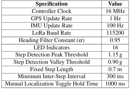
Table 1: System Specifications
VIII.TEST SETUP
- The device is powered using a portable battery
- GPS coordinates are acquired in outdoor
- Fixed campus locations and remote peer devices are selected as navigation targets.
- Multiple devices exchange coordinates using LoRa communication.
- Localization is validated by deliberately blocking GPS reception and verifying that the distance estimate continues to update correctly as the user walks toward the target.
- Navigation accuracy is verified by physical movement to-ward targets and comparison of LED-indicated direction with the physical target direction.
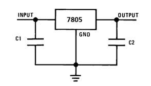
Figure 8: 7805 regulator to power TM4C via 9V battery
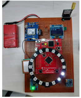
Figure 9: Implementation of the electronic compass
IX.CONCLUSION
This project presented the design and implementation of a TM4C123-based smart navigation and location-sharing system integrating GPS, IMU, magnetometer, OLED visualisation, LED-based directional guidance, and LoRa wireless communication.
Sensor fusion using accelerometer, gyroscope, and magnetometer measurements enabled robust heading estimation, while GPS-based calculations provided accurate distance and bearing information.
The custom LoRa communication protocol enabled long-range coordinate exchange between multiple devices without relying on internet connectivity.
The successful implementation demonstrates the effective-ness of embedded sensor fusion, localization implementation, and wireless communication for portable navigation applications.
REFERENCES
- Texas Instruments, TM4C123GH6PM Microcontroller Data Sheet, 2024.
- InvenSense, MPU6050 Product Specification,
- QST Corporation, QMC5883P Magnetometer Datasheet,
- Semtech Corporation, LoRa Technology Overview,
- NMEA Association, NMEA 0183 Standard,
- Shin, H. Cha, and K. Kim, Pedestrian Dead Reckoning System with Step Detection and Heading Estimation, IEEE Sensors Journal, vol. 18, no. 3, pp. 1139–1148, 2018.
- Mahony, T. Hamel, and J.-M. Pflimlin, Nonlinear Complementary Filters on the Special Orthogonal Group, IEEE Transactions on Automatic Control, vol. 53, no. 5, pp. 1203–1218, 2008.
Recent Comments