
ABSTRACT
Efficient plant care requires continuous monitoring of soil moisture and ambient light, especially when multiple plants must be controlled independently. Manual watering and lighting are often inconsistent, and simple timer-based systems cannot respond to real time environmental changes. This paper presents the design and implementation of a two-plant smart irrigation and grow-light control system based on the TM4C123GH6PM microcontroller. The project uses a distributed embedded architecture in which a field node senses plant conditions and controls actuators, while a receiver node communicates with a desktop graphical user interface (GUI). The two Tiva C boards communicate through a Controller Area Network (CAN) bus, allowing robust message exchange between the sensor-actuator side and the control-room side.
The field node monitors two soil moisture inputs, two light dependent resistor (LDR) circuits, two relay-driven pump motors, and two LED grow-light outputs. Automatic mode allows the field node to make local decisions using embedded threshold logic, including pump activation for dry soil, forced pump shutoff below a low moisture safety threshold, and smart evening light timers. Manual mode transfers control authority to the control room, allowing the user to directly command pumps and LEDs while the field node continues to report live telemetry. The receiver node acts as a CAN-to-UART bridge, forwarding telemetry to a Python Tkinter GUI and transmitting GUI control commands back to the field node. The final implementation demonstrates a modular smart agriculture prototype with real-time monitoring, dual-mode operation, independent
plant control, and a clear operator dashboard.
Keywords: Embedded Systems, TM4C123GH6PM, CAN Bus, Smart Irrigation, LDR, Soil Moisture Sensor, Relay Control, Automatic Control, Manual Override.
I.INTRODUCTION
Agricultural automation and plant monitoring systems are becoming increasingly important in domestic gardening, greenhouse control, and precision agriculture. A plant’s growth depends strongly on two continuously changing physical parameters: soil moisture and light intensity. If soil remains dry for along duration, the plant experiences water stress. If light availability is insufficient, photosynthesis is reduced. Conversely,
excessive watering or continuous artificial light can also damage plant health. Therefore, a useful smart farming system must not simply switch loads on and off blindly; it must respond to sensor feedback and preserve an appropriate balance between irrigation, lighting, and rest periods.
The objective of this project is to develop a two-plant smart irrigation and grow-light prototype that can monitor and control both plants independently. Each plant is associated witha moisture sensor, an LDR-based light sensor, a pump motor controlled through a relay module, and an LED used as a supplemental grow light. The system is designed around two TM4C123GH6PM Tiva C LaunchPad boards. The field node is placed near the plants and performs sensing and actuation. The receiver node is connected to the laptop and communicates with the user.
A key requirement of the project is that the system must support both automatic and manual operation. In automatic mode, the field node must control the motors and LEDs using threshold logic without requiring continuous commands from the user. In manual mode, control must be transferred to the control room, and the field node must stop making autonomous control decisions. This separation is important because auto
matic operation is useful for unattended plant care, while manual mode is necessary for testing, demonstration, and emergency override.
The project uses Controller Area Network (CAN) communication between the two Tiva boards. CAN was selected because it is robust, message-oriented, and commonly used in embedded systems requiring reliable communication between distributed nodes. The receiver node converts CAN telemetry into UART text messages that can be parsed by the Python GUI. The GUI displays moisture values, LDR values, pump states, LED states, and the current control mode. It also provides manual control buttons that become active only in manual mode.
The implemented system includes several practical control features. Pump motors turn on when moisture values indicate dry soil, turn off when moisture drops below the wet threshold, and are forcefully kept off when moisture falls below 2500. The LDR logic turns LEDs on in dim light and off in sufficient light. A “Smart Sunrise” style timer limits evening supple mental light: Plant 1’s LED remains on for 5 seconds after darkness is detected, while Plant 2’s LED remains on for 10 seconds. Once the timer expires, the LED enters a sleep period until daylight resets the cycle. Although these short times are chosen for demonstration, the same logic can be scaled to hours in a real deployment.
II.THEORETICAL BACKGROUND
The system combines sensing, digital control, serial communication, CAN networking, and relay-based power switching. This section summarizes the engineering concepts required to understand the implementation.
2.1 Soil Moisture Sensing
Resistive soil moisture sensors estimate soil water content by measuring the electrical conductivity between two exposed probes. Wet soil generally conducts better than dry soil, producing a sensor output that changes with water content. Many low-cost moisture sensor modules provide both an analog output (AO) and a digital comparator output (DO). In this project, analog moisture measurement is used so that the microcontroller can observe a full range of values rather than a single binary state.
The TM4C123GH6PM contains a 12-bit Analog-to-Digital Converter (ADC), producing values from 0 to 4095. A higher moisture reading in this project corresponds to a drier condition. Therefore, pump logic is written using high values as dry-soil triggers. The threshold values used in the final implementation are:
• Pump ON if moisture >3000
.• Pump OFF if moisture <2500.
The gap between 3000 and 2500 creates hysteresis, preventing the pump from rapidly switching on and off when the sensor value fluctuates near a single threshold.
2.2 LDR Light Sensing
Alight dependent resistor changes resistance according to incident light intensity. Since a bare LDR has only two terminals, it cannot be connected directly to an ADC input by itself. It must be used as part of a voltage divider. The implemented circuit uses the LDR and a fixed resistor to create a variable analog voltage at the ADC pin. When ambient light changes, the voltage at the divider midpoint changes, allowing the ADC to measure light intensity.
The final LED control thresholds are:
• LEDONifLDRvalue <2800.
• LEDOFFifLDRvalue >3200.
This arrangement turns LEDs on when the environment is dim and turns them off when light is sufficient. The dead band between 2800 and 3200 avoids flickering caused by small light variations.
2.3 Relay-Based Motor Control
The pump motors are controlled through relay modules be cause a TM4C GPIO pin cannot directly supply the current required by a motor. The GPIO pin drives the relay input, while the relay contact side switches the motor’s external supply. This electrically separates low-power logic control from higher-current motor operation. The correct wiring principle is that the Tiva board should not power the motor from its USB VBUS rail. The motor supply must be external, and all grounds must be common only where needed for signal reference. The motor current should return directly to the external supply ground rather than flowing through the Tiva board.
2.4 CAN Communication
Controller Area Network (CAN) is a multi-master serial communication protocol designed for reliable embedded networking. It uses message identifiers rather than device addresses. In this project, the field node and receiver node exchange messages over CAN0. The field node sends sensor telemetry and status messages, while the receiver sends control commands. The main CAN identifiers are:
• 0x10: Telemetry message containing moisture and LDR values.
• 0x11: Status message containing mode, pump states, and LED states.
• 0x20: Control message containing manual mode and manual control bits.
Using separate identifiers for telemetry, status, and commands makes the system modular and easier to debug.
III .YSTEM ARCHITECTURE
The project follows a distributed two-node architecture. One Tiva board acts as the field node and the second Tiva board acts as the receiver/control-room node. The field node owns all sensors and actuators. The receiver node owns the USB serial connection to the laptop.
3.1 Field Node
The field node performs the following tasks:
• Reads Plant 1 moisture sensor.
• Reads Plant 2 moisture sensor.
• Reads Plant 1 LDR voltage divider.
• Reads Plant 2 LDR voltage divider.
• Controls Pump 1 relay.
• Controls Pump 2 relay.
• Controls LED 1 and LED 2.
• Sends telemetry and actuator status over CAN.
• Receives automatic/manual mode and manual command bits over CAN.
3.2 Receiver Node
The receiver node is the interface between the CAN bus and the laptop. Its responsibilities are:
• Receive telemetry frames from the field node.
• Receive status frames from the field node.
• Print structured status lines over UART for the GUI.
• Receive user commands through UART.
• Convert user commands into CAN control frames.
3.3 Desktop GUI
The Python Tkinter GUI provides a control-room dashboard.It displays:
• Control mode: Automatic or Manual.
• Plant 1 moisture, pump state, LDR value, and LED state.
• Plant 2 moisture, pump state, LDR value, and LED state.
• Receiver serial log.
• Manual control buttons for pumps and LEDs.
Manual buttons are enabled only in manual mode. This ensures that the GUI does not conflict with automatic field-node decisions.
IV.HARDWARE DESIGN AND PIN MAPPING
The system hardware was designed to keep all sensing and actuation on the field side while keeping the receiver side electrically simple. This reduces wiring complexity between the plants and the laptop.
4.1 Field Node Connections
The field node pin mapping is shown in Table 1. These are the active project connections used by the smart farm prototype.
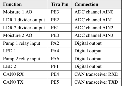
Table 1: Field Node Pin Mapping
4.2 Receiver Node Connections
The receiver node uses fewer pins because it does not directly read sensors or drive actuators. Its primary hardware connections are shown in Table 2.
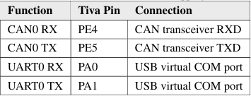
Table 2: Receiver Node Pin Mapping
4.3 LDR Voltage Divider
Each LDR is connected as a voltage divider. For Plant 1:
3.3V →LDR1→PE2→10kΩ→GND (1)
For Plant 2:
3.3V →LDR2→PE1→10kΩ→GND (2)
The ADC reads the midpoint voltage and converts it into a digital value. The LED control logic then compares this value against the dark and bright thresholds.
4.4 Power Distribution
The most important hardware rule is that the Tiva USB VBUS line must not supply the motors. The motors and relay modules require a stable external supply. A common ground reference is required so that GPIO signals are interpreted correctly by the relay module, but motor current must not return through the Tiva board.
V.COMMUNICATION PROTOCOL
The field node and receiver node exchange fixed-format CAN messages. The GUI does not directly communicate over CAN. Instead, it sends simple ASCII commands to the receiver through UART, and the receiver converts them into CAN command frames.
5.1 Telemetry Frame
The field node sends sensor values using CAN identifier 0x10. The message length is 8 bytes. Four 12-bit ADC values are packed as four unsigned 16-bit values:
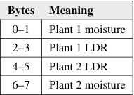
Table 3: Telemetry CAN Frame: ID 0x10
Each sensor value is transmitted in big-endian format, with the high byte first and low byte second.
5.2 Status Frame
The field node sends actuator and mode status using CAN identifier 0x11. This frame contains one byte of flags.
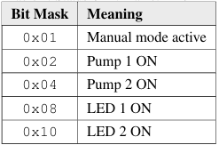
Table 4: Status CAN Frame: ID 0x11
5.3 Control Frame
The receiver sends control commands using CAN identifier 0x20. The first byte represents the mode, while the second byte contains manual control bits.
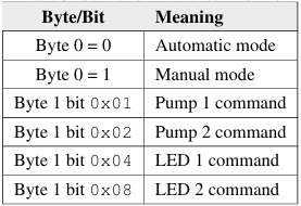
Table 5: Control CAN Frame: ID 0x20
VI.CONTROL LOGIC
6.1 Automatic Mode
In automatic mode, the field node makes all control decisions locally. The receiver and GUI only display telemetry and status. This is important because the plants should continue to be cared for even if the laptop GUI is disconnected.
The pump logic for both plants is:
Pump ONif Moisture >3000
Pump OFFif Moisture <2500
6.2 LED Smart Evening Timer
The LED logic is based on the LDR value. If the LDR value is below 2800, the system treats the condition as dim or dark. If the value rises above 3200, the system treats it as sufficient light.
When darkness is detected, the LED turns on and an evening timer starts. Plant 1’s LED remains on for 5 seconds and Plant 2’s LED remains on for 10seconds. After the timer expires, the LED turns off and remains in sleep mode until a new bright light condition resets the cycle. This demonstrates the concept of supplemental evening light without eliminating the plant’s dark cycle.
6.3 Manual Mode
In manual mode, the field node stops using automatic thresh old decisions. The control room becomes the source of control. The user can switch Pump 1, Pump 2, LED 1, and LED 2 from the dashboard. The field node still reads sensors and reports telemetry, but it obeys the manual command bits from the receiver node.
This design ensures that there is no conflict between automatic logic and manual control. At any instant, ownership of the outputs belongs either to the field node’s automatic logic or to the manual controls.
VII.SOFTWARE DESIGN: FIELD NODE
The field-node firmware is written in Bare-Metal C using TivaWare driver APIs. The software is organized around peripheral initialization, interrupt service routines, sensor acquisition, output control, and CAN message publishing.
7.1 Initialization
During startup, the field node performs the following initialization sequence:
1. Configure the system clock.
2. Enable GPIO ports A, E, and F.
3. Configure PA2, PA4, and PA6 as digital outputs.
4. Configure PF1 as a digital output.
5. Configure PE3, PE2, PE1, and PE0 as ADC inputs.
6. Configure CAN0 pins PE4 and PE5.
7. Initialize CAN0 at 500 kbps.
8. Configure CAN receive mailbox for control messages.
9. Configure CAN transmit messages for telemetry and status.
10. Enable interrupts and start periodic sampling.
7.2 ADC Sampling
ADC sequence 1 is configured to read four analog channels.
The sequence order is:
• Step 0: Plant 1 moisture.
• Step 1: Plant 1 LDR.
• Step 2: Plant 2 LDR.
• Step 3: Plant 2 moisture.
After conversion, the ADC interrupt handler stores the readings, evaluates automatic or manual behavior, updates GPIO outputs, and publishes the new state over CAN.
7.3 CAN Receive Handling
The field node listens for CAN command frames with identifier 0x20. When such a frame arrives, the CAN interrupt handler extracts the mode byte and manual command bits. If the mode is manual, the field node immediately applies the received command bits to the pumps and LEDs.
7.4 Output Update
The field node updates the outputs by writing the corresponding GPIO pins:
• PA2drives Pump 1 relay.
• PA6drives Pump 2 relay.
• PA4drives LED 1.
• PF1 drives LED 2.
This separation keeps plant outputs independent and makes debugging easier.
VIII.SOFTWARE DESIGN: RECEIVER NODE
The receiver-node firmware is also written in Bare-Metal C. It serves as a protocol bridge between CAN and UART.
8.1 CAN Reception
The receiver listens for two CAN message IDs. Telemetry frames with ID 0x10 contain the sensor readings. Status frames with ID 0x11 contain actuator and mode flags. Once these frames are received, the receiver formats a structured UART line for the GUI.
The GUI expects lines in the following format:
![]()
Listing 1: GUI Status Line Format
This text format is intentionally human-readable. It simplifies debugging through a serial monitor and also makes GUI parsing straight forward.
8.2 UART Command Handling
The GUI sends ASCII commands to the receiver. Examples include:
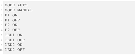
Listing 2: GUI Command Examples
The receiver parses these commands and updates its mode or manual command bits. It then sends a CAN control frame to the field node.
8.3 Interrupt-Driven Structure
The final firmware avoids placing control logic inside the main loop. The main function initializes peripherals and then idles. Peripheral activity is handled through interrupts:
• CAN interrupts process incoming telemetry, status, and control messages.
• UART interrupts process GUI command input.
• ADC interrupts process completed sensor conversions.
• Timer/SysTick activity schedules repeated sampling.
This design matches embedded-system best practice by allowing the processor to respond quickly to hardware events rather than continuously polling.
IX.TESTING AND RESULTS
The prototype was tested progressively by isolating each subsystem. First, the moisture and LDR sensor readings were verified through the serial monitor. Next, relay modules were tested without motors to confirm GPIO control. After that, motors were connected through the relay contact side using an external supply. Finally, CAN communication and GUI control were tested.
9.1 Sensor Testing
Plant 1 and Plant 2 moisture readings were observed while placing sensors in water and removing them into air. The readings changed significantly, confirming that the ADC path was operational. LDR values were tested by covering and uncovering the LDRs. The LED behavior was adjusted so that LEDs turn on under dim conditions and turn off under sufficient light.
9.2 Relay and Motor Testing
The relay modules were first tested without motors. This verified that the Tiva GPIO output could trigger the relay input. When motors were connected, power stability became critical. It was found that powering motor-related modules from the Tiva VBUS could pull the voltage down and cause instability. The final stable setup uses an external supply for relay and motor power, with common ground reference.
9.3 CAN Testing
The CAN bus successfully transferred telemetry and status data from the field node to the receiver. The GUI displayed sensor values and output states in real time. Manual mode was verified by switching pumps and LEDs from the GUI. Automatic mode was verified by allowing the field node to control outputs based on sensor thresholds.
9.4 Observed Performance
The project achieved the following behaviors:
• Independent control of two plants.
• Automatic pump control based on moisture thresholds.
• Force-off safety condition below 1500 moisture reading.
• LDR-based LED activation in dim light.
• Timed supplemental light for both plants.
• Manual GUI override for all pumps and LEDs.
• CAN-based communication between field and receiver nodes.
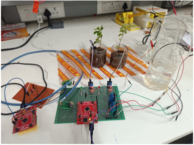
Figure 1: Prototype testing showing the two Tiva boards, CAN transceivers, sensors, relay modules, pumps, LEDs, and external power supply
X.LIMITATIONS AND FUTURE SCOPE
10.1 Limitations
The current prototype is a local smart farm system. The GUI must be connected to the receiver node through a serial COM port, and it does not yet provide remote access through Wi-Fi or cloud services. The threshold values are currently fixed in firmware, so changing them requires code modification and re-flashing. Sensor calibration is also dependent on the specific moisture sensor modules and soil conditions used during testing.
Another limitation is that low-cost resistive moisture sensors can corrode over time due to electrolysis if continuously powered. For long-term deployment, capacitive soil moisture sensors would be more reliable.
10.2 Future Scope
Future improvements can include:
• Editable thresholds directly from the GUI.
• Data logging of moisture and light trends.
• Wi-Fi or cloud dashboard integration.
• Mobile notification when soil becomes dry.
• Capacitive moisture sensors for improved durability.
• Real-time clock support for actual hour-based light scheduling.
• PCB design for stable wiring and reduced breadboard noise.
XI.CONCLUSION
This project successfully demonstrates a two-plant smart irrigation and grow-light system using two TM4C123GH6PM microcontrollers, CAN communication, relay-driven pump control, and LDR-based light sensing. The distributed architecture separates field sensing and actuation from control-room visualization, making the system modular and easier to debug. Automatic mode allows the field node to care for plants using embedded thresholds and timer logic, while manual mode gives the user full control. The final prototype validates the practical integration of ADC sensing, GPIO actuation, CAN communication, and safe external motor power wiring. It also highlights important embedded-system design lessons, including the need for hysteresis, stable power distribution, and clear ownership between automatic and manual control modes. Overall, the system provides a strong foundation for a scalable smart agriculture platform.
REFERENCES
[1] Texas Instruments, TM4C123GH6PM Microcontroller Data Sheet, Literature Number: SPMS376E, Austin, TX, USA, 2014.
[2] Texas Instruments, TivaWare Peripheral Driver Library User’s Guide, Texas Instruments, 2014.
[3] Robert Bosch GmbH, CAN Specification Version 2.0, Stuttgart, Germany, 1991.
[4] J. W. Valvano, Embedded Systems: Introduction to ARM Cortex-M Microcontrollers, 5th ed. Austin, TX, USA: Independently published, 2014.
[5] Texas Instruments, TM4C123x UART Peripheral Documentation, included in TM4C123GH6PM data sheet and TivaWare reference material.
[6] Texas Instruments, TM4C123GH6PM ADC Module Documentation, included in TM4C123GH6PM Microcontroller Data Sheet.
[7] Songle Relay, SRD Series Relay Datasheet, commonly used 5V relay module reference.
Recent Comments