
ABSTRACT
Traditional mechanical access control systems are increasingly inadequate for modern security paradigms, primarily due to their lack of active deterrence, intelligent multi-factor authentication, and comprehensive autonomous event logging [5]. This paper presents the design, theoretical foundation, and hardware implementation of a highly integrated Smart Door Security and Surveillance System. To achieve real-time deterministic control without compromising heavy multimedia processing capabilities, the system employs a distributed, hybrid microcontroller architecture [1], [2]. A TM4C123GH6PM (Tiva C) ARM Cortex-M4F microcontroller operates as the master control unit. It executes critical Bare-Metal C firmware to manage passive infrared (PIR) motion detection, matrix keypad inputs, optical biometric authentication via an AS608 sensor, and localized hardware actuation for the locking mechanism. To circumvent the inherent memory and processing constraints of the Cortex-M4F regarding multimedia tasks, an ESP32 CAM module is interfaced as an asynchronous surveillance coprocessor [2]. Connected via a synchronized Universal Asynchronous Receiver-Transmitter (UART) communication link utilizing 16-byte hardware FIFOs, the ESP32-CAM captures high fidelity UXGA photographic evidence upon receiving intrusion triggers and logs the data to a localized FAT32 MicroSD card. This report details the underlying operational theory, precise circuit routing, algorithmic debouncing techniques, non-blocking software state machines, and the successful deployment of a modular, highly secure access control prototype that bridges deterministic actuation with asynchronous multimedia logging [5].
Index Terms—Embedded Systems, TM4C123GH6PM, ESP32 CAM, UART Protocol, Access Control, Hardware FIFO, Optical Biometrics, AS608, PWM Actuation.
I.INTRODUCTION
The evolution of physical security infrastructure has witnessed a distinct paradigm shift from passive, mechanical locking mechanisms to active, intelligent electronic access control systems [5]. In residential, commercial, and highly sensitive research environments, a standard mechanical deadbolt is no longer sufficient to guarantee spatial integrity. Modern security vectors demand multi-factor authentication (MFA)—combining what a user knows (a digital PIN) with what a user is (topographical biometrics)—coupled with autonomous surveillance that can log suspicious activity without requiring continuous human oversight [5].
The primary objective of this project is to engineer a localized, highly secure smart door prototype that seamlessly fuses these requirements: deterministic biometric and PIN access control alongside automated visual event logging [1],[2].
However, developing such a system on a monolithic, single microcontroller architecture presents significant embedded engineering challenges. Microcontrollers designed for precise, real-time hardware actuation, such as the Texas Instruments TM4C123GH6PM (Tiva C), excel at rapid state-machine execution, Pulse Width Modulation (PWM) generation, and interrupt-driven peripheral control [1]. Conversely, they are fundamentally constrained by limited static RAM (32 KB SRAM) and lack the native computational throughput required to efficiently initialize dense camera sensors, buffer high resolution JPEG frames, and manage the complex FAT file systems required for Secure Digital (SD) card storage. Attempting to force an ARM Cortex-M4F to handle intensive multimedia tasks inevitably leads to processor bottlenecking, which can critically delay time-sensitive security functions such as sounding an alarm.
Alternatively, utilizing a Single Board Computer (SBC) like a Raspberry Pi introduces its own flaws: lengthy operating system boot times, high power consumption, and the inherent timing jitter of a non-real-time OS, which can severely disrupt sensitive PWM signals required for mechanical locks. To resolve this computational bottleneck, this project proposes and implements a distributed, hybrid-microcontroller architecture [1], [2]. The philosophy of this design is rooted in strict task delegation. The TM4C123GH6PM is deployed strictly as a deterministic master controller. It runs a Bare Metal C environment without a Real-Time Operating System
(RTOS), ensuring that sensor polling, biometric processing, and user interface updates occur with absolute temporal predictability [1], [5].
Simultaneously, an ESP32-CAM module is integrated as an asynchronous, dedicated surveillance co-processor [2]. The ESP32-CAM leverages its dual-core Tensilica Xtensa architecture and integrated pseudo-static RAM (PSRAM) to exclusively handle the initialization of the OV3660 camera sensor and the execution of SD card write cycles [2], [8]. The communication bridge between these two disparate computational environments is achieved through a carefully synchronized, bidirectional UART link.
By decoupling the deterministic security logic from the asynchronous multimedia logging, the system achieves a highly responsive, fault-tolerant operational flow [5]. This paper extensively documents the theoretical and practical realization of this system. Section II establishes the theoretical background governing UART mechanics, pyroelectric sensing, and optical biometrics. Section III details the overarching system architecture. Section IV explores the specific hardware component selections, power distribution routing, and circuit design. Section V dissects the inter-processor communication. Sections VI and VII analyze the software algorithms driving both the Tiva C and the ESP32-CAM. Finally, Sections VIII through X discuss the overarching operational workflow, physical testing results, and the future scope for scaling this localized prototype into a fully integrated Internet of Things (IoT) security network [2].
II.THEORETICAL BACKGROUND
The realization of this hybrid security system depends on the precise integration of several distinct engineering domains: asynchronous serial communication, thermodynamic sensing, and optical biometrics.
A. UART Protocol Mechanics and Synchronization
Universal Asynchronous Receiver-Transmitter (UART) is a hardware peripheral that translates data between parallel and serial forms. Because UART does not utilize a shared clock line, the transmitting and receiving devices must operate at a pre-agreed baud rate to successfully frame data bits, start bits, and stop bits [6]. The UART peripheral oversamples the incoming signal, typically at 16 times the baud rate, to accurately detect the center of each data bit and avoid framing errors caused by minor clock drifts.
The TM4C123GH6PM operates on a default 16 MHz system clock. To establish reliable communication with the AS608 Fingerprint sensor and the PC Debug console at 57,600 baud, the Baud Rate Divisor (BRD) is calculated based on the system clock frequency (fsys):
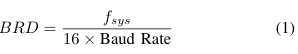
For a baud rate of 57,600:
![]()
The integer portion (IBRD = 17) is loaded into the UART_IBRD_R register. The fractional portion is multiplied by 64 and rounded to the nearest integer to determine the Fractional Baud Rate Divisor (FBRD):
![]()
Similarly, to communicate with the ESP32-CAM at a higher speed of 115,200 baud, the required divisor is 8.6805, resulting in an IBRD of 8 and an FBRD of 44. To prevent data frame degradation during high-speed UART bursts, the 16 byte hardware First-In-First-Out (FIFO) buffers are enabled on the Tiva C by setting the UART_LCRH_R register to 0x70, which allows the processor to temporarily ignore incoming serial traffic while handling critical tasks without losing data [1].
B. Passive Infrared (PIR) Thermodynamic Sensing
The system utilizes an HC-SR501 PIR sensor to detect the presence of individuals at the door [4]. The sensor relies on a pyroelectric sensor, which generates a differential surface charge when exposed to changes in infrared radiation.
The human body naturally emits infrared radiation with a peak wavelength of approximately 9.4 µm. The HC-SR501 contains a dual-element array placed behind a multifaceted Fresnel lens. The Fresnel lens serves to expand the sensor’s field of view and focus incoming IR energy directly onto the sensor elements. When ambient background radiation strikes both elements equally, the voltages cancel each other out, preventing false positives from sunlight or ambient room heating. However, when a human crosses the sensor’s field of view, it sequentially intercepts the two elements, creating a positive, then negative, differential pulse. This analog anomaly is amplified by an onboard BISS0001 signal processing IC, which drives the sensor’s digital output pin HIGH. The TM4C123G polls this pin (PD0) to register motion events [4].
C. Optical Biometric Topography
The AS608 biometric module operates on the principle of Total Internal Reflection (TIR) [3]. When a finger is placed on the glass platen, an internal LED illuminates the surface. The ridges of the fingerprint physically touch the platen, frustrating the total internal reflection and absorbing light, while the valleys remain untouched and reflect light back into a solid state CMOS image sensor.
The sensor’s internal DSP extracts specific minutiae points (bifurcations, ridge endings, and short ridges) rather than storing a raw photograph of the fingerprint. This mathematical representation significantly reduces the required storage space and drastically lowers the False Acceptance Rate (FAR) while optimizing the False Rejection Rate (FRR). During the enrollment phase, the system demands two independent scans
to increase template fidelity. These scans generate intermediate character files (cmd_Img2Tz1 and cmd_Img2Tz2). A localized algorithm then maps the topographical variance between these two files, synthesizing a unified Reg Model template that is permanently stored in the sensor’s flash memory.
III.SYSTEM ARCHITECTURE
To maximize efficiency and responsiveness, the system’s architecture is explicitly bifurcated into two specialized processing domains: the Master Controller and the Surveillance Node [1], [2]. This master-slave topology eliminates the risk of memory buffer overflows that commonly occur when a single microcontroller attempts to juggle both hardware interrupts and heavy multimedia streams.
A. Master Controller Domain (TM4C123GH6PM)
The Tiva C Launchpad functions as the central deterministic hub of the system [1]. Operating without an RTOS, it executes a strict, non-blocking polling loop. The Master Controller is exclusively responsible for:
• Input Polling: Continuously monitoring the PIR sensor for infrared disturbances and scanning the 4×4 matrix keypad for manual PIN entry via a row-column sweep [1].
• Biometric Delegation: Sending hex-encoded instruction packets to the AS608 sensor and parsing the returned confirmation bytes to verify user identity [3].
• Surveillance Triggering: Issuing the serial ”CAPTURE” command over UART1 to wake the ESP32-CAM when an intrusion or failed access attempt is detected [2].
B. Surveillance Node Domain (ESP32-CAM)
The ESP32-CAM operates as an asynchronous slave device dedicated entirely to visual logging [2]. It waits in a low power standby state until it receives a trigger from the Master Controller. Upon receiving the string ”CAPTURE” via its UART RX pin (GPIO3), the ESP32-CAM executes a high level routine to initialize the OV3660 camera, capture a JPEG frame, mount the FAT file system, and append the image to the MicroSD card via the SD_MMC library [7], [8]. By offloading the heavy lifting of image processing and SD card block-writing delays to the ESP32, the Tiva C remains completely free to continue scanning the keypad and monitoring the door, ensuring zero computational lag in physical security enforcement.
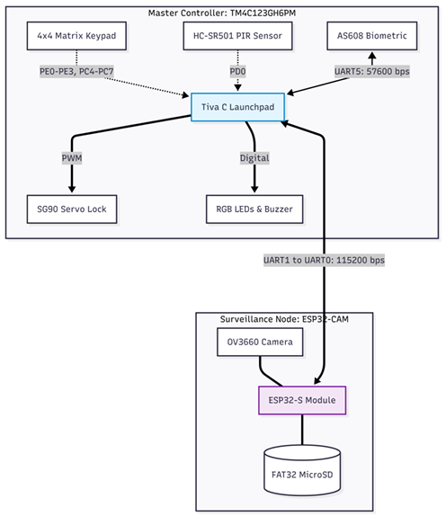
Fig. 1. The bifurcated hybrid system architecture, illustrating the deterministic control zone (Tiva C) and the asynchronous multimedia zone (ESP32-CAM), linked via UART [6].
IV.HARDWARE SELECTION AND CIRCUIT DESIGN
The physical realization of this hybrid architecture relies on selecting components that offer high reliability, adequate processing overhead, and compatible logic voltage thresholds. The circuit design prioritizes signal integrity and power stability, particularly regarding the transient current spikes generated by the ESP32-CAM’s radio module. [1].
A. Microcontroller Selection
• Master Controller (TM4C123GH6PM): An ARM Cortex-M4F based microcontroller operating at 16 MHz. It features 256 KB of Flash memory, 32 KB of SRAM, and a dedicated Floating-Point Unit (FPU). Its abundance
of hardware UART modules, internal pull-up resistors, and deterministic execution make it ideal for orchestrating time-sensitive security states.
• Surveillance Node (ESP32-CAM): A highly integrated development board featuring the ESP32-S chip (dual core 32-bit LX6 microprocessor), an OV3660 camera module (UXGA 1622×1200 resolution), and an onboard MicroSD card slot [2]. It is utilized exclusively for its multimedia and storage capabilities.
B. Sensor and Actuator Integration
• AS608 Optical Fingerprint Sensor: A DSP-driven biometric module [3]. It utilizes a 5V power supply but features 3.3V tolerant UART logic, allowing direct connection to the Tiva C (PE4, PE5) without the need for
external bidirectional logic level shifters.
• HC-SR501 PIR Sensor: Tuned via onboard potentiometers for a delay time of approximately 3 seconds and a sensitivity range of 5 meters. Its digital output is routed to Tiva pin PD0 with an internal pull-down resistor enabled [4].
• 4×4 Matrix Keypad: A passive membrane switch array. To minimize hardware components, internal pull-up resistors are enabled on the Tiva’s column pins (PC4-PC7), yielding a logic LOW when a switch connects a column to an actively driven LOW row pin (PE0-PE3) [1].
C. Power Distribution and Signal Integrity
Proper power management is critical to prevent system resets or brownouts. The Tiva C is powered via its USB debugging interface (providing 5V to the onboard regulators). However, the ESP32-CAM draw significant transient currents.
The ESP32-CAM, during camera initialization or MicroSD card write cycles, can draw current spikes exceeding 500mA. To prevent voltage droop, a dedicated 5V external power supply is utilized for the ESP32-CAM, and the AS608 sensor. A 470 µF electrolytic decoupling capacitor is placed across the ESP32-CAM’s 5V and GND rails to supply instantaneous current and stabilize the voltage [2]. Crucially, all power supplies and microcontroller grounds are tied together to establish a common zero-voltage logic reference level across the entire system [5].
V.INTER-MICROCONTROLLER COMMUNICATION AND UART INTEGRATION
The success of the hybrid architecture depends entirely on the reliability of the communication link between the TM4C123G and the ESP32-CAM [1], [2]. A loss of data here would result in a failure to capture photographic evidence of an intrusion.
A. UART Link Configuration
The physical link utilizes UART1 on the Tiva C and UART0 on the ESP32-CAM [1], [2]. The pin mapping is exactly as follows:
• Tiva CPB1(U1TX) connects to ESP32 GPIO3 (U0RX) [2].
• Tiva CPB0(U1RX) connects to ESP32 GPIO1 (U0TX) [2].
The baud rate is configured to 115,200 bps to ensure rapid command transmission while maintaining signal integrity over breadboard jumper wires. Both devices are configured for standard 8-N-1 formatting (8 data bits, no parity, 1 stop bit).
B. Hardware FIFO and Buffer Management
When the AS608 fingerprint sensor transmits 16-byte biometric templates, or when the PC debug console is flooded with system logs, the Tiva C’s serial registers can quickly overflow if relying solely on a software polling loop. To mitigate this, the 16-byte hardware First-In-First-Out (FIFO) buffer is enabled on all active UART modules (UART0, UART1, and UART5) via the UART_LCRH_R register.
Listing 1. Hardware FIFO Enablement
UART5_LCRH_R = 0x70; // 8-bit word length, FIFOs enabled
UART5_CTL_R |= 0x301; // Enable UART, TX, and RX
This hardware buffering acts as an elastic data repository, allowing the Tiva C to execute its matrix keypad debouncing loops without losing incoming serial data from the biometric sensor. To manage stale or corrupted data from interrupted scans, soft flush and hard flush routines (UART5_HardFlush) were implemented to drain the FIFO completely before sending critical commands to the AS608.
C. Command Packetization
The protocol utilized between the Tiva C and ESP32-CAM is based on simple, human-readable ASCII string packetization. When a triggering event occurs (e.g., motion detected or unauthorized access), the Tiva C transmits the literal string “CAPTURE\n” [6].
The ESP32-CAM firmware utilizes the Arduino Serial.readStringUntil(’\n’) function to parse the incoming stream [7]. This newline-terminated protocol is deliberately chosen over single-byte flags. It prevents the ESP32 from capturing partial commands and ensures structural synchronization even if rogue bits are introduced by electrical noise on the breadboard.
VI.SOFTWARE DESIGN: MASTER CONTROLLER (TM4C123G)
The firmware for the TM4C123G was developed in Code Composer Studio utilizing a Bare-Metal C paradigm [1], [5]. By eschewing a Real-Time Operating System (RTOS), the system guarantees deterministic execution, operating as a continuous polling loop with tightly controlled temporal parameters [5].
A. Non-Blocking Temporal Control (Polled SysTick)
Standard software delays, such as busy-wait loops, completely halt processor execution. This severely cripples a security system that must simultaneously monitor a PIR sensor, a keypad, and incoming serial buffers [1]. To achieve non blocking delays and timeout tracking without the overhead of context-switching, the ARM Cortex SysTick timer is utilized in a polled configuration rather than an interrupt-driven one. This approach deliberately avoids Interrupt Service Routine (ISR) naming conflicts and prioritization complexities. The SysTick timer is initialized with a reload value of 15,999:
Listing 2. SysTick Initialization for 1ms Polling
void SysTick_Init(void) {
NVIC_ST_CTRL_R = 0;
NVIC_ST_RELOAD_R = 15999;
NVIC_ST_CURRENT_R = 0;
NVIC_ST_CTRL_R = 0x05;
}
At a 16 MHz system clock, this configuration triggers the COUNT flag exactly every 1 millisecond. The main loop continuously calls a tick_update() routine, which increments a global volatile uint32_t time_ms variable. This global timestamp acts as the foundational temporal baseline for all system timeouts, camera cooldowns, and switch debouncing algorithms [5].
B. Matrix Keypad Algorithmic Debouncing
Mechanical switch bounce introduces high-frequency electrical oscillations that can cause a single keypad press to register as multiple erratic inputs. A robust debouncing state machine was implemented utilizing the time_ms baseline to ensure clean data acquisition [5].
The algorithm evaluates the raw input matrix continuously. It requires a key’s electrical state to remain stable for 50 milliseconds (key_change_time) before it is validated as a legitimate press. Once temporal stability is confirmed, the system enforces a 250-millisecond lockout window (last_press_time) before accepting another input. This entirely eliminates phantom double-entries while maintaining a highly responsive user interface for rapid PIN entry.
C. Biometric Enrollment State Machine
The AS608 biometric integration utilizes advanced error handling and multi-step state machines. Fingerprint enrollment is a complex procedure requiring the synthesis of a topographical template from two distinct high-resolution captures. The master controller executes the following strict sequence [3]:
1) Image 1 Capture: Issue cmd_GenImg (0xEF0x01…) to capture the initial topological map.
2) Minutiae Extraction 1: Issue cmd_Img2Tz1 to mathematically extract the minutiae points into the sensor’s internal Buffer 1.
3) Image 2 Capture: Wait for the user to lift and replace their finger, then repeat the capture process for Buffer 2(cmd_Img2Tz2).
4) Template Synthesis: Issue AS608_RegModel to algorithmically merge the two buffers into a high-fidelity verification model.
5) Non-Volatile Storage: Issue cmd_Store1 to save the generated template to the sensor’s localized flash memory for persistent storage [3].
Because biometric scans are highly prone to user error (e.g., partial prints, wet fingers, or insufficient pressure), the firmware employs ”silent receive loops.” If the sensor returns a 0x02 (No Finger) or 0x0A (Templates Mismatch) error code, the Tiva C safely flushes the UART5 hardware FIFO via UART5_HardFlush() and prompts the user to retry. This critical fault-tolerance mechanism prevents the main security loop from entering a hard fault or freezing due to a corrupted biometric scan.
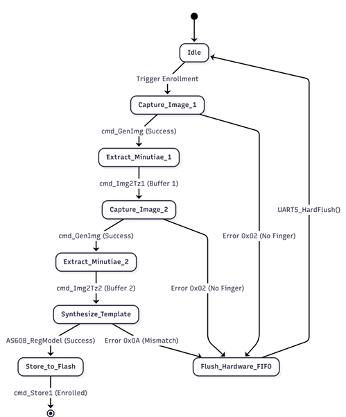
Fig. 2. State diagram illustrating the AS608 biometric enrollment process, including hardware FIFO flush fallbacks for read errors
VII.SOFTWARE DESIGN: SURVEILLANCE NODE (ESP32-CAM)
The ESP32-CAM firmware, developed via the Arduino IDE [7], is designed for asynchronous multimedia execution. The node remains in a low-power listening state, minimizing thermal throttling, until it is explicitly triggered by the master controller [2].
A. UART Command Parsing
The ESP32-CAM utilizes its hardware serial port (mapped to GPIO3/RX) to monitor the 115,200 baud serial link. Itparses incoming streams looking for the newline-terminated string “CAPTURE\n” [6]. Relying on newline termination rather than single-byte fixed frames prevents the ESP32 from capturing corrupted or partial commands induced by environmental electrical noise.
B. File System and Camera Execution
Upon validation of the CAPTURE command, the ESP32CAM immediately allocates a frame buffer in its PSRAM utilizing the esp_camera.h API [7], [2]. It commands the OV3660 sensor to capture a UXGA resolution JPEG. Concurrently, the firmware mounts the SD_MMC FAT32 file system [8]. The JPEG buffer is written to the MicroSD card with a sequentially generated filename [8]. Once the file stream is closed, the ESP32 releases the frame buffer from PSRAM to prevent memory leaks and gracefully returns to its standby state [2].
VIII.SYSTEM WORKFLOW AND OPERATIONAL LOGIC
The overarching system workflow is governed by an infinite while(1) loop within the Tiva C firmware that continuously evaluates environmental vectors against the system’s embedded security logic [5].
A. Intrusion Detection and Surveillance Cooldown
During normal operation, the system continuously monitors the PIR sensor [4]. If the PIR_MotionDetected() function returns true, the system checks a boolean flag. If the camera is not currently cooling down, the system immediately transmits the camera trigger via UART1 to the ESP32-CAM[6].
To prevent flooding the SD card with hundreds of redundant photos of a single continuous event, the system institutes a non-blocking 12-second cooldown (camera_cooldown_end = time_ms + 12000;). During this window, subsequent PIR triggers are deliberately ignored by the Tiva C, allowing the ESP32-CAM ample time to finalize SD card block-write cycles without overlapping interruption [2], [8].
B. Authentication Resolution
The core access control logic hinges on user input via the matrix keypad (a 4-digit PIN) or the AS608 biometric scanner [3].
• Access Granted: Upon matching the hardcoded PIN or successfully verifying a fingerprint template via cmd_Search, the system resets the wrong_attempts counter to zero [5]. The Tiva C illuminates the Green LED for 3 seconds before returning to a locked, armed state [1].
• Access Denied: An invalid PIN entry or an unknown fingerprint scan instantly triggers the Red LED [1]. Crucially, the Tiva C simultaneously transmits the CAPTURE command to the ESP32-CAM, forcing it to log the visual identity of the unauthorized user attempting to breach the system [2]. The wrong_attempts counter is then incremented.
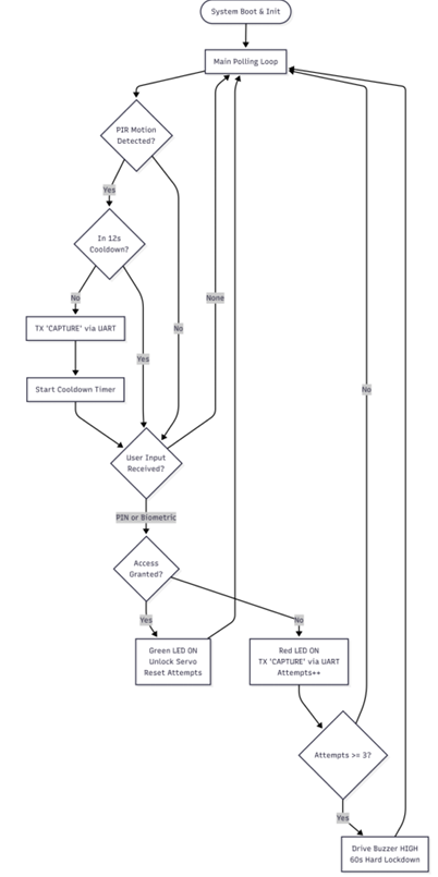
Fig. 3. Comprehensive operational flowchart detailing the Master Controller’s infinite polling loop, authentication branching, and ESP32-CAM UART triggering [1], [2].
• Alarm Lockdown State: If the wrong_attempts threshold reaches or exceeds 3 consecutive failures, the system enters a hard lockdown [5]. A 60-second non blocking timeout is initiated, and the Piezo Buzzer is
driven HIGH to sound an audible alarm [1]. During this lockdown, all keypad and biometric inputs are completely ignored, effectively mitigating brute-force attacks [5].
IX.TESTING, RESULTS AND STATUS INDICATION
Extensive physical testing validated the efficacy of the hybrid architecture. Visual feedback proved critical for seamless user interaction, mapping directly to the onboard RGB LEDs of the TM4C123G [1].
A. User Interface Feedback Mapping
• Blue LED: Indicates active motion detection, confirms a camera capture has been triggered, or denotes that the system is currently in administrator enrollment mode [3].
• Green LED: Indicates successful biometric or PIN authentication, confirming the door is unlocked, or signaling a successful return to the armed standby state [1].
• Red LED: Indicates access has been denied, the door remains locked, or signals an active buzzer alarm state following multiple failed attempts [5].
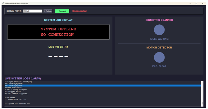
Fig. 4. Custom Smart Home Security Dashboard displaying live UART0 system logs, sensor statuses, and simulated PIN entry
B. Performance Metrics
Testing confirmed that the 16-byte hardware FIFO implementation successfully prevented UART packet loss during simultaneous keypad entry and intensive fingerprint scanning [1], [6]. Furthermore, the ESP32-CAM successfully processed, compressed, and stored UXGA JPEGs within approximately 2.5 seconds of receiving the Tiva’s command. This processing time falls comfortably within the 12-second system cooldown window, proving the system is highly stable and devoid of race conditions.
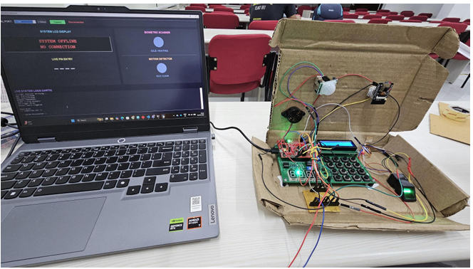
Fig. 5. Complete hardware testing environment demonstrating the PC-based dashboard interfaced with the physical hardware prototype via USB
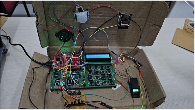
Fig. 6. Close-up view of the localized hardware prototype, highlighting the Tiva C Launchpad, ESP32-CAM, PIR sensor, matrix keypad, and AS608 biometric scanner
X.LIMITATIONS, FUTURE SCOPE AND CONCLUSION
A. Limitations
While the prototype excels at localized physical security, its primary limitation is its lack of remote network connectivity [2]. Photographic logs currently require the physical, manual extraction of the MicroSD card to be viewed, preventing real-time visual alerts from reaching an administrator [2]. Additionally, the system lacks dynamic user management; modifying the master PIN currently requires recompiling and flashing the Tiva C firmware.
B. Future Scope
Future iterations of this system will actively exploit the ESP32-CAM’s onboard 802.11 b/g/n WiFi stack. The surveillance node’s firmware will be upgraded to push captured JPEGs directly to a cloud infrastructure, such as an AWS S3 bucket or a Telegram bot API, providing administrators with real-time push notifications on their mobile devices [2]. Furthermore, edge-computed facial recognition algorithms could be deployed natively on the ESP32 to cross-reference the biometric verification occurring on the Tiva C, creating a highly advanced three-factor authentication matrix [2], [3].
C. Conclusion
This project successfully synthesizes deterministic access control logic and automated visual surveillance through a highly efficient hybrid microcontroller design [1], [2]. By offloading complex FAT file system management and heavy multimedia processing to the ESP32-CAM, the TM4C123G master controller retains the absolute deterministic predictability required to enforce physical security [1]. The resulting Smart Door Security prototype is robust, modular, and serves as an excellent demonstration of asynchronous inter-processor UART communication in advanced embedded systems [5].
REFERENCES
[1] Texas Instruments, TM4C123GH6PM Microcontroller Data Sheet, Literature Number: SPMS376E, Austin, TX, USA, 2014.
[2] Espressif Systems, ESP32-S Series Hardware Manual, Version 1.2,Shanghai, China, 2020. [Online]. Available: https://www.espressif.com/
[3] Hangzhou Synochip Data Security Technology Co., Ltd., AS60x OpticalFingerprint Sensor Module User Manual, Version 2.1, 2018.
[4] BISS0001 Micro Power PIR Motion Detector IC Datasheet, Components Info, 2015. [Online]. Available for HC-SR501 Module.
[5] J. W. Valvano, Embedded Systems: Introduction to ARM Cortex-M Microcontrollers, 5th ed. Austin, TX, USA: Independently published, 2014.
[6] Standardization Sector of ITU, Data Communication over the Telephone Network: Asynchronous to Synchronous Conversion, ITU-T Recommendation V.14, 1993.
[7] Arduino, Arduino IDE and ESP32 Core Documentation. [Online]. Available: https://github.com/espressif/arduino-esp32
[8] SD Association, SD Specifications Part 1 Physical Layer Simplified Specification, Version 6.00, 2018
Recent Comments