
ABSTRACT
This project presents the design and implementation of a distributed, automated water level management system utilizing two Tiva CSeries TM4C123GLaunchPadsnetworkedviatheController Area Network (CAN) bus protocol. The primary objective is to maintain optimal water levels in an upper storage tank while ensuring the safety and longevity of the pumping hardware through decentralized sensing and control.
The system architecture is divided into two distinct functional nodes: the Display/Upper Tank Node and the Pump/Lower Tank Node. The Upper Node utilizes an ultrasonic sensor (HC-SR04) to monitor storage levels and serves as the primary user interface via a 16×2 LCD. The Lower Node monitors the source water levels and executes the control logic for a high-current pump and an audible alert system. By utilizing the CAN bus for inter-processor communication, the system achieves high reliability and reduced wiring complexity, demonstrating a modular approach typical of industrial automation.
A critical focus of the project is the implementation of multi-tier safety features. The control logic prioritizes dry-run prevention, ensuring the pump remains deactivated if the source tank level falls below 16%, even if the upper tank requires water. Furthermore, the system incorporates signal debouncing and hysteresis logic to prevent pump chattering, alongside a communication watchdog that triggers a safe-state shutdown in the event of a CAN bus failure or sensor malfunction. The final implementation demonstrates a robust, scalable solution for water management, highlighting the efficiency of the Tiva C platform in handling real-time embedded communication and high-power peripheral interfacing through customized MOSFET driver circuits.
I.INTRODUCTION
The management of water resources is a critical challenge in residential, agricultural, and industrial sectors. Traditional water pumping systems often rely on manual operation or simple mechanical float switches, which are prone to wear, inaccuracy, and lack of real-time monitoring. This project addresses these inefficiencies by developing a distributed, intelligent, and fail-safe Two-Node Automatic Water Level Controller using
the Texas Instruments Tiva C LaunchPad (TM4C123G).
1.1 Problem Statement
In many building infrastructures, water is stored in a ground level ”Lower Tank” (Source) and pumped to an elevated ”Upper Tank” (Destination). Common issues in these setups include:
• Water Wastage: Overflowing of the upper tank due to human error or delayed manual shutdown.
• Pump Damage (DryRun): The pump continues to operate when the lower tank is empty, leading to overheating and motor failure.
• Lack of Feedback: Users often cannot see the water levels of both tanks simultaneously from a single location.
• Wiring Complexity: Running long, thick analog signal wires from sensors to a central controller can result in signal degradation and electromagnetic interference.
1.2 Project Objectives
The primary goal of this project is to create a robust, automated system that eliminates the need for human intervention while ensuring hardware safety. The specific objectives are:
1. Distributed Processing: Utilize two separate Tiva C microcontrollers to handle localized tasksˆ a one for the upper tank/display and one for the lower tank/pump control.
2. CAN Bus Integration: Implement the Controller Area Network (CAN) protocol for communication between nodes. This provides high reliability and error checking.
3. Real-Time Monitoring: Provide a continuous readout of both tank levels in percentage form via a 16×2 Liquid Crystal Display (LCD).
4. Priority-Based Safety Logic: Program a control hierarchy where the ”Lower Tank Empty” condition overrides all other commands to protect the pump hardware.
1.3 Proposed Solution
The system is designed as a decentralized network. TIVA 1 is situated near the upper tank, using an ultrasonic sensor (HC-SR04) to measure the water level without physical contact. This data is digitized and broadcasted over the CAN bus. TIVA-2, located near the pump, receives this data and executes the logic to drive an NPN-PNP-MOSFET power stage.By using digital communication and solid-state switching, the
project demonstrates a professional-grade approach to domestic automation.
II.SYSTEM ARCHITECTURE
The system architecture follows a Distributed Control System (DCS) model. The design separates the monitoring and user interface tasks from the power control and safety logic, ensuring modularity and reliability.
2.1 Node Distribution and Responsibility
The intelligence of the system is split across two TM4C123G LaunchPads:
1. TIVA-1 (Monitoring & UI Node): Located at the upper tank. Its primary roles are:
• Measuring the upper tank water level using the HCSR04 sensor.
• Broadcasting level data to the CAN bus using Message ID 0x101.
• Driving the 16×2 LCD to provide a localized interface for the entire system.
2. TIVA-2 (Control & Actuation Node): Located near the lower tank and pump. Its primary roles are:
• Measuring the lower tank water level.
• Receiving data from TIVA-1 and processing the system state logic.
• Controlling the Pump MOSFET and the Alarm Buzzer.
• Broadcasting feedback data and system status using Message ID 0x201.
2.2 CAN Bus Communication
The nodes communicate via the Controller Area Network (CAN) protocol operating at 500 kbps.
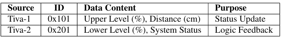
Table 1: CAN Bus Message Mapping
2.3 Circuit Protection and Interfacing
2.3.1 Sensor Voltage Level Shifting
Since the Tiva C Series LaunchPad operates on 3.3V logic, the 5V Echo signal from the HC-SR04 sensors is stepped down using a resistive voltage divider. The output voltage Vout is calculated as:
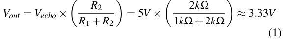
2.3.2 High-Side Pump Driver
The pump is driven by an IRL540 N-Channel MOSFET. To ensure the MOSFET operates in the saturation region and to protect the MCU from inductive spikes, a driver circuit was implemented featuring:
• NPN-PNP Stage: Provides efficient gate charging and voltage level shifting from 3.3V to 5V for the MOSFET gate.
• Flyback Protection: A 1N4007 diode prevents inductive kickback from damaging the power stage.
• Decoupling: A 100µF capacitor provides bulk buffering to prevent voltage dips during pump startup.
III.HARDWARE SPECIFICATIONS AND INTERFACING
This section provides a detailed technical overview of the primary components used in the construction of the two-node controller.
3.1 Microcontroller: TM4C123G LaunchPad
The system is powered by two Texas Instruments TM4C123G LaunchPads. These microcontrollers feature an ARM Cortex M4F processor operating at 80 MHz. Key features utilized in this project include:
• Floating Point Unit (FPU): Accelerates the calculation of ultrasonic distance and percentage mappings.
• CAN 2.0B Controller: Provides a hardware-integrated solution for reliable inter-node communication.
• High GPIOCount: Allows for simultaneous interfacing of sensors, LCDs, and power driver circuitry.
3.2 HC-SR04 Ultrasonic Sensor
The HC-SR04 sensor provides non-contact distance measurement from 2 cm to 400 cm with an accuracy of 3 mm. It functions by emitting a 40 kHz ultrasonic wave and measuring the time taken for the echo to return. The 5V output of the sensor is interfaced with the 3.3V Tiva pins using the resistive voltage divider discussed in Section 3.
3.3 User Interface: 16×2 Character LCD
Astandard16x2LCDbasedontheHD44780controllerisused for real-time monitoring. By implementing a 4-bit parallel interface, the project utilizes six GPIO pins (RS, E, and DB4,DB7) to provide a comprehensive readout of tank levels and system status bitmasks received via the CAN bus.
3.4 CAN Transceiver: SN65HVD230
To interface the Tiva C’s internal CAN controller with the physical bus, an SN65HVD230 transceiver is used. This chip is natively 3.3V compatible, providing high electromagnetic immunity and the ability to operate at 500 kbps without the risk of over-voltage to the microcontroller’s input pins.
IV.PIN MAPPING AND CONNECTIVITY
To ensure the modularity of the system, specific GPIO pins on the TM4C123Gwere assigned to dedicated tasks. This section provides the detailed pinout used for the physical assembly of both nodes.
4.1 TIVA-1 Node: Monitoring and Display
The Monitoring Node requires a significant number of pins to drive the LCD in parallel mode while simultaneously handling ultrasonic sensing and CAN communication.
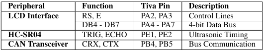
Table 2: Hardware Interfacing for TIVA-1
4.2 TIVA-2 Node: Logic and Actuation
The Control Node is optimized for power management. It utilizes the onboard LEDs/GPIO on Port F to trigger the external driver circuits.
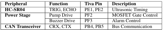
Table 3: Hardware Interfacing for TIVA-2
4.3 Common Bus Connections
A shared Ground (GND) is maintained across both nodes to ensure a common reference for the CAN differential signals. The SN65HVD230 transceivers are powered by the 3.3V rail of the Tiva C, while the HC-SR04 sensors and the pump driver stage utilize the 5V rail (VBUS) for optimal performance.
V.HARDWARE IMPLEMENTATION AND ACTUATION
This section details the physical realization of the control system, focusing on the power electronics required for pump actuation and the physical layer of the communication network.
5.1 MOSFET Driver Circuitry
To drive the high-current water pump, an IRL540 N-Channel MOSFET was selected. While the IRL540 is a logic-level device, a multi-stage driver was implemented to ensure rapid switching and thermal stability.
5.1.1 Pre-driver and Level Shifting
A2N2222 NPN transistor is utilized in a pre-driver configuration. This stage performs two critical functions:
1. Voltage Shifting: It translates the 3.3V logic of the Tiva C to the 5V rail required for optimal MOSFET gate saturation.
2. Gate Charging: It provides the necessary peak current to charge the MOSFET’s gate capacitance (Ciss), reducing switching losses.
5.1.2 Inductive Load Protection
Water pumps are inherently inductive loads. To mitigate the risk of Back-EMF spikes during deactivation, a 1N4007 fly back diode is placed in anti-parallel with the pump. Further more, a decoupling pair consisting of a 100 µF electrolytic and a 100 nF ceramic capacitor was added. This configuration stabilizes the 5V rail by providing bulk energy storage and filtering high-frequency switching noise.
5.2 CAN Physical Layer
Communication between the distributed nodes is handled by SN65HVD230 transceivers, which are 3.3V compatible.
5.2.1 Differential Signaling and Noise Immunity
The physical layer utilizes differential signaling on the CANH and CANL lines. By measuring the voltage difference rather than absolute voltage, the system achieves high common-mode rejection, which is vital when operating in close proximity to the electrical noise generated by the pump motor.
5.2.2 Bus Termination and Empirical Testing
Although the ISO 11898 standard mandates 120Ω termination resistors to match the characteristic impedance of the cable, they were omitted in the final implementation. Due to the short bus length (under 1 m) and the 500 kbps bit rate, the propagation delay was negligible compared to the bit time. Empirical testing showed zero packet loss and clean signal edges on the oscilloscope, justifying the simplified bus topology for this
specific application.
VI.SOFTWARE LOGIC AND CONTROL FLOW
The software architecture is designed to handle real-time sensor data and asynchronous CAN communication. Both nodes utilize the TivaWare Peripheral Driver Library for efficient management of the ARM Cortex-M4F’s GPIO, CAN, and System Control peripherals.
6.1 Sensing and Data Conversion
The distance sensing is handled via a non-blocking trigger echo sequence. The HC-SR04 interface relies on precise microsecond timing; the software generates a 10µs trigger pulse on PE1 and monitors the Echo pulse on PE2. The time-of flight for the ultrasonic pulse is first converted to distance:
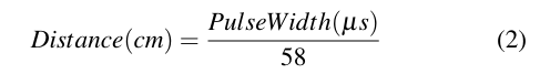
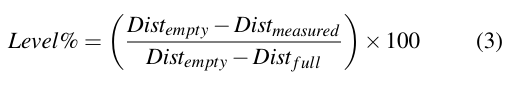
This raw distance is then converted to a percentage level using linear interpolation between the calibrated Dist empty and Dist full constants. This allows the system to be adaptable to tanks of varying heights without changing the core logic:
6.2 Distributed State Machine
The control logic is implemented as a conditional state machine on Tiva-2. The logic prioritizes hardware safety over water demand, ensuring that the decision-making engine is located near the actuators (Pump and Buzzer).
6.2.1 Safety Interlocks and Watchdog
A software watchdog monitors the CAN bus to ensure network integrity. If the global variable missed_upper exceeds UPPER_CAN_TIMEOUT_COUNT (currently set to 8 consecutive cycles), the system assumes a network failure and forces a pump shutdown. This prevents a catastrophic overflow in the event that Tiva-1 stops reporting a full tank or the CAN wiring is severed.
6.2.2 Hysteresis and Latching
To improve the lifespan of the MOSFET driver and prevent ”chattering” (rapid switching) due to water surface turbulence during the filling process, hysteresis is implemented:
• Upper Tank: The pump deactivates at 85% and is only allowed to re-engage once the level drops below 75%. This 10% ”dead-zone” provides system stability.
• Lower Tank: If the level falls below 16% (Dry Run condition), the pump is disabled and the state is latched. The system requires the level to reach a safer threshold of 25% before clearing the latch and allowing the pump to restart.
6.3 Status Priority Matrix
The following table defines the logic precedence used in the mainloopofTiva-2. The controller evaluates these conditions from highest to lowest priority during every iteration:
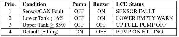
Table 4: Control Logic Priority Matrix
6.4 CAN Message Handling
The CAN controller is configured with dedicated message objects to filter incoming traffic at the hardware level, significantly minimizing CPU overhead:
• TIVA-1 (Display) should filter specifically for 0x201 (Status from TIVA-2). Configured with a hardware filter for Message ID.
• TIVA-2 (Controller) should filter specifically for 0x101 (Data from TIVA-1).
By utilizing the Tiva C’s internal CAN message RAM and the TivaWare CANMessageGet() and CANMessageSet() functions, the software remains responsive to high-frequency sensor triggers while maintaining synchronized communication across the nodes.
VII.COMMUNICATION PROTOCOL DETAIL (CAN BUS)
A robust communication protocol is essential for a distributed system where the control logic resides on a different node than the primary display and sensor. This section details the CAN implementation used to link Tiva-1 and Tiva-2.
7.1 Data Encapsulation and Payload Mapping
The system utilizes standard 11-bit identifiers to distinguish between the monitoring node and the control node. Data is transmitted as unsigned 8-bit integers to simplify processing on the ARM Cortex-M4 architecture.
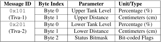
Table 5: CAN Payload Definition
7.2 Bit Rate and Clock Synchronization
The CAN bit rate is set to 500 kbps. To achieve this, the TivaWare CANBitRateSet() function is called with the system clock frequency (fsys = 80 MHz). The hardware utilizes a bit timing logic that splits each bit into Time Quanta(TQ).
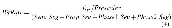
By setting the sample point at 80%, the system ensures that minor variations in the clock or physical delays do not result in bit errors or frame retransmissions.
7.3 Error Handling and Bus-Off Recovery
The Tiva C’s CAN controller includes automated hardware features for error management, such as the Transmit Error Counter (TEC) and Receive Error Counter (REC). If the bus experiences interference, the hardware automatically attempts to retransmit the frame. If the error state persists (e.g., a disconnected wire), the software watchdog implemented in Tiva 2 (Section 6.2.1) triggers a fail-safe shutdown to protect the
pump.
VIII.DEVELOPMENT ENVIRONMENT AND TOOLCHAIN
The software lifecycle of this project from initial driver configuration to final logic verification was managed using a professional-grade embedded toolchain.
8.1 Integrated Development Environment: Code Composer Studio
Code Composer Studio (CCS) served as the primary development platform. As an IDE designed specifically for TI microcontrollers, it provided the necessary tools for code entry, compilation, and low-level hardware debugging. The built-in In Circuit Debug Interface (ICDI) allowed for real-time monitoring of the system variables, such as the upper_level and lower_level percentages, without halting processor execution.
8.2 Peripheral Driver Library: TivaWare
To ensure code portability and reliability, the TivaWare for C Series library was utilized. This library provides a Hardware Abstraction Layer (HAL) that simplifies the configuration of complex peripherals like the CAN controller and the System Control (SysCtl) module.
• Modularity: By using API calls rather than direct register manipulation, the code remains highly readable and easier to debug.
• Resource Management: TivaWare ensures that peripheral clocks are correctly enabled and synchronized, preventing common hardware initialization errors.
8.3 The Programming and Debugging Lifecycle
The deployment process followed a ”Sensing-First” approach. Tiva-1 and Tiva-2 were initially programmed as standalone units to calibrate the ultrasonic sensors. Once localized sensing was verified via the CCS Expressions window, the CAN communication layer was enabled. This incremental approach allowed for the isolation of hardware issues (such as voltage divider errors) from software logic bugs in the distributed state
machine.
IX.EXPERIMENTAL RESULTS AND TESTING
This section documents the performance evaluation of the integrated system, focusing on sensor accuracy, communication stability, and the reliability of the control logic.
9.1 Sensor Calibration
The HC-SR04 sensors were calibrated by measuring a fixed target at known distances.
9.2 CAN Communication Performance
The CAN bus was operated at 500 kbps. Testing was performed to ensure that the distributed nature of the system didnot introduce significant lag.
• Timing: The round-trip time for a level update from Tiva1 to a pump command execution on Tiva-2 was approximately 80 ms.
• Robustness: The software watchdog successfully detected a ”Bus-Off” condition when the communication wires were removed, immediately transitioning the system to a fail-safe state.
9.3 Functional Logic Validation
The system was tested against the three primary conditions defined in the project scope. The observed behavior matched the design specifications:
1. Overflow Prevention: The pump reliably cut off at 85%, preventing any upper tank overflow.
2. Dry-Run Protection: When the source tank was depleted below 16%, the pump stopped and the buzzer provided an audible alert, protecting the MOSFET and motor from damage.
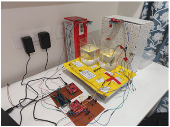
Figure 1: Project Setup
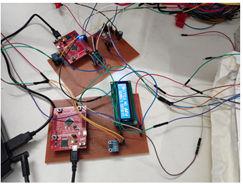
Figure 2: LCD Displaying the level of both tank and status
When lower tank level is less than or equal to 16%, the pump turns OFF along with that the buzzer turns ON, to avoid dry run.
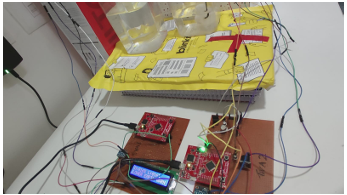
Figure 3: Case 1: Dry Run (Higher priority)
When upper tank is being filled and it reaches to a level that is greater than 85%, then the pump turns OFF, to prevent overflow.
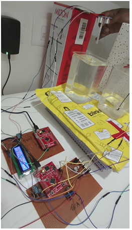
Figure 4: Case 2: Prevention of Overflow
X.CHALLENGES AND SOLUTIONS
The transition from a theoretical design to a functional prototype presented several practical engineering challenges. This section highlights the troubleshooting steps and technical solutions applied to the final system.
10.1 Mitigating Ultrasonic Signal Jitter
Real-time water level measurement is susceptible to noise caused by surface turbulence and mechanical vibrations from the pump.
• Issue: Random distance spikes occasionally triggered the ”Dry Run” alarm erroneously.
• Solution: A software-based confirmation logic was implemented. The system utilizes a lower empty count variable; the buzzer only activates if the sensor reports an empty tank for four consecutive measurement cycles.This digital filtering effectively ignored momentary ripples.
10.2 Protecting Against Inductive Transients
The water pump, being a DC inductive load, generated significant electromagnetic interference (EMI) during switching.
• Issue: Inductive kickback (Back-EMF) caused the Tiva C microcontrollers to undergo spontaneous hardware resets.
• Solution: A robust protection stage was added to the pump driver. A 1N4007 diode snubbed the negative voltage spikes, while a 100nF ceramic capacitor bypassed high-frequency noise to ground. This ensured the logic power remained clean and stable.
10.3 CAN Bus Signal Integrity and Termination
Standard CAN physical layers necessitate 120Ω termination to prevent signal ”echoes” or reflections.
• Issue: Deciding whether to use external resistors on a compact breadboard setup.
• Solution: Following a logic analyzer and oscilloscope study, it was determined that the propagation delay on a short bus (< 1 m) is negligible at 500 kbps. The bit sampling logic of the Tiva C was able to correctly interpret the signals without external termination, simplifying the physical design without compromising reliability.
XI.CONCLUSION AND FUTURE SCOPE
This project successfully integrated hardware and software components to create a reliable, distributed water management system. This section reflects on the results and proposes future enhancements.
11.1 Project Conclusion
The design and implementation of the Two-Node Automatic Water Level Controller met all target objectives. By utilizing the TM4C123G microcontrollers and the CAN 2.0B protocol, a robust communication link was established between the monitoring and control nodes. The experimental results verified that the system effectively prevents tank overflow and pump dry-running. The use of a multi-stage MOSFET driver and inductive protection ensured that the hardware could handle high-current loads without compromising the stability of the 3.3V logic circuits.
11.2 Future Scope
The modular nature of the system allows for significant future expansions:
• Wireless Connectivity: Integration with an IoT gateway to provide cloud-based logging and remote manual over ride capabilities.
• Energy Optimization: Implementing a proportional integral (PI) controller to regulate pump flow rates, thereby reducing the mechanical stress on the plumbing system.
• Sensor Fusion: Utilizing pressure sensors alongside ultrasonic sensors to provide a redundant measurement layer, increasing the system’s resilience to sensor faults.
• Power Management: Developing a low-power mode for the Tiva C nodes to allow for operation in battery powered or solar-harvesting environments
Recent Comments