
Senior citizens often suffer accidental falls due to their diminished self-care and self-protection ability. These accidents may possibly have serious consequences if no aid is given in time. Statistics show that the majority of serious consequences are not the direct result of the falls, but rather are due to a delay in assistance and treatment after a fall. In the event of a fall, the danger of post-fall consequences can be greatly reduced if relief personnel can be alerted in time. In light of this, there has been increased development of devices for detection and prediction of fall situations.
These fall detectors operate on the principle of detecting changes in body position when moving by tracking acceleration changes in three orthogonal directions of an individual wearing a sensor. The data is then analyzed algorithmically to determine whether the individual’s body is falling. The core part of the fall detector is therefore the detection principle and the algorithm to judge the existence of an emergency fall situation.
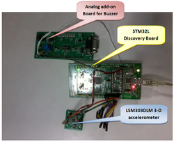
STM32L Discovery Board Details
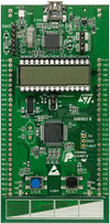
STM32L basic board
The STM32L Discovery board is based on an STM32L152RBT6 and includes on-board ST-Link/V2 debug interface. As can be seen from the picture, most of the General Purpose I/Os (GPIOs) are brought out for use towards the sides of the board.
The main features of the board which were used in this project are:
- The external 3V supply pin which can be used to provide power to Buzzer and Accelerometer add-on boards
- The GPIO ports brought out to sides of the board
- Built-in I2C module
Accelerometer Add-On board
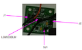
Accelerometer Add-On Board
The Accelerometer add-on board has the following features:
- 3-axis Magnetometer
- 3-axis Accelerometer
Only the Accelerometer is used presently in this project.
Features Used:
- Analog supply voltage: 2.16V to 3.6V
- Power-down mode
- 3 acceleration channels
- ±2g/±4g/±8g dynamically selectable full-scale
- I2C serial interface
The schematic of the add-on board can be found here :Accelerometer_Schematic
-
Analog Add-On board
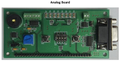
Analog Add-On Board
The Analog add-on board has the following features:
- Temperature Sensor
- Buzzer
- LED array
- DIP switches
- USART
- Anti-Tamper and Wakeup unit
Only the buzzer is used to indicate fall.
The schematic of the add-on board can be found here : Analog_Schematic
-
Interconnection Details

Interconnection
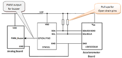
The Accelerometer Add-On Board has File:LSM303DLM_Datasheet which has both 3-axis magnetometer and 3-axis accelerometer. The interface to this IC is via I2C1 of STM32 board. The peripheral board address is 0x18. The board is powered using 3V Ext Output from the STM32 Board.
The following are the connections to be made between the STM32 Board and the Add-On Boards:
Accelerometer Board: Acc
STM32 Board : STM
Analog Board: An
Sr.No. Source Destination Remarks 1. STM.EXT_3V Acc.J1.1 3V Supply to Accelerometer Board 2. STM.GND Acc.J1.2 GND to Accelerometer Board 3. STM.PB9 Acc.J2.2 I2C1-SDA of STM32 to SDA of Accelerometer Board 4. STM.PB8 Acc.J2.1 I2C1-SCL of STM32 to SCL of Accelerometer Board 5. STM.EXT_3V An.J.3 3V Supply to Analog Board 6. STM.GND An.J.2 GND of Analog board 7. STM.PA0 An.J.6 GPIOA0 of STM32 to PWM_Buzzer of Analog Board Acceleration Change Characteristics during the Fall Process
Acceleration Change Curves during the Process of Falling
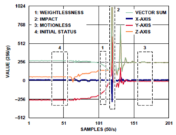
The main research on the principles of fall detection focuses on the acceleration change characteristics during the process of a human body falling as shown in figure.
There are four critical characteristics of a falling event. These four characteristics can be used as the criterion of the fall detection. They are marked by the boxes in figure and explained in detail as follows.
Initial Status (Marked by Box 4)
This period denotes the normal activities performed by user where the accelerometer works in low-power mode.
Weightlessness (Marked by Box 1)
Weightlessness always occurs at the start of a fall. This phenomenon becomes more significant during free-fall, and the vector sum of acceleration reduces to near 0 g, the duration depends on the height of the free-fall. Even though weightlessness during an ordinary fall is not as significant as that during a free-fall, the vector sum of acceleration is also less than 1 g (generally greater than 1 g under normal conditions). Therefore, this is the first basis for determining the fall status.
Impact (Marked by Box 2)
After experiencing weightlessness, the human body makes impact with the ground; the acceleration curve shows this as a large shock in figure. Therefore, this is the second basis for determining a fall.
Motionless (Marked by Box 3)
Generally, the human body, after falling and making impact, cannot rise immediately. Instead, it remains in a motionless position for a short period. This is shown on the acceleration curve as a segment of a flat line in figure. But if this period is greater than a threshold value, then the fall is detected.
The sequence of these four bases of determination form the entire fall detection algorithm, and then the system can raise an alert accordingly for the fall status. The time interval between these stages must be within a reasonable range. The detection thresholds and time parameters for each stage can be flexibly set as needed.
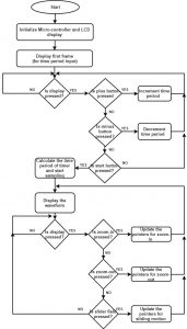
Basic Algorithm
1. After initialization, the system continuously receives x, y and z acceleration values from LSM303DLM accelerometer over I2C
   interface with sample rate of 10 samples/sec (low power mode) and calculates resultant according to formula:
              vect_sum=sqrt(x^2+y^2+z^2)
2. If vect_sum< 0.75g, free fall is detected and system waits for impact event. The system mode is changed to normal mode (50
   samples/sec) for accurate detection of impact event.
3. If impact is not detected within 10 sec, the free fall event is considered as false alarm and system goes back to free fall
   detection.
4. If impact event is detected (vect_sum > 2g) before timeout, the system waits for 1 sec to damp out acceleration changes due to
   impact.
5. The system continues to receive x, y and z acceleration values from accelerometer to detect if any activity is made by the wearer.
6. If no activity is detected within 10 sec, the fall is confirmed and buzzer is enabled else system goes back to free fall
   detection mode.
Flow Chart
-
-
Points to be noted
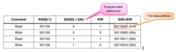
Slave Address (SAD) and read/write patterns
- Out of 7-bit slave address for the accelerometer LSM303DLM, first 6 bits are fixed with a programmable lower bit. R/W is changed accordingly.
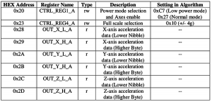
- Following table presents the function of each register and the values used in the present algorithm. Data sheets can be referred for detailed definitions of each register bit. Some of the registers presented in table have two algorithm setting values. This indicates that the algorithm switches between these two values to achieve different detection purposes.
-
Project Team
- Shrutee Kamat
- Harshita Agrawal

Recent Comments