
ABSTRACT
This report details the design and implementation of a real-time health monitoring system capable of measuring heartrate (BPM), blood oxygen saturation (SpO2), and body temperature. The system is built around an ARM Cortex-M4 microcontroller (TM4C123GXL). It integrates a MAX30102 optical sensor and an MLX90614 infrared thermopile multiplexed on a shared I2C bus. A custom digital signal processing (DSP) pipeline extracts clinical vital signs from noisy optical data. The architecture supports simultaneous dual-telemetry, providing wireless Bluetooth transmission to a mobile application and high-speed USB streaming to a PC dashboard for live visualization.
I.INTRODUCTION
The objective of this project is to design and build a real time health monitoring system capable of accurately measuring a patient’s heart rate (BPM), blood oxygen saturation (SpO2), and body temperature. Acquiring clean plethysmographic signals in real-time presents significant challenges due to motion artifacts and ambient light interference.
To address these challenges, the system employs advanced Digital Signal Processing (DSP) algorithms executed on the edge device. Furthermore, to enable comprehensive moni toring, the system implements simultaneous dual-telemetry: wireless Bluetooth to a mobile app, and high-speed USB to a PC dashboard.
II.SYSTEM ARCHITECTURE
The system architecture relies on an ARM Cortex M4 microcontroller interfacing with high-precision medical sensors.
The core components include the TM4C123GXL Launchpad, an MLX90614 temperature sensor, a MAX30102 pulse oximeter, an SSD1306 OLED display, and an HC-05 Bluetooth module.
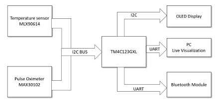
Figure 1: System Architecture
2.1 Hardware Integration
A critical hardware design choice was the implementation of a Shared I2C Bus Architecture. To optimize GPIO usage on the microcontroller, the system successfully multiplexed the MLX90614 (Address 0x5A) and the MAX30102 (Address 0x57) on the same I2C0 bus using pins PB2 and PB3.Data from the sensors is subsequently transmitted over two separate UART interfaces to achieve the PC Live Visualization and mobile telemetry.
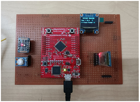
Figure 2: Physically assembled Health Monitoring hardware prototype
III.FIRMWARE IMPLEMENTATION
The firmware is designed around a highly deterministic, non-blocking finite state machine (FSM) utilizing a super loop architecture.
3.1 Sensor Initialization and Control
The MAX30102 sensor is initialized via I2C to optimize clinical data acquisition. The firmware configured hardware averaging to 4 samples, the sampling rate to 100 Hz, and the LED pulse width to 411us. To optimize tissue penetration, the optical output is driven by precision-pulsing the Red LED at 7.6 mA (Register 0x0C) and the IR LED at 12.5 mA (Register 0x0D).
3.2 Main Execution Loop
The code implementation follows a strict sequence:
1. Main Super Loop entry
2. Check for MAX30102 FIFO: If data is ready, proceed.
3. Data Acquisition: Execute an I2C0 read burst to extract raw ADC values from the 18-bit Data FIFO.
4. Finger Detection: If raw_ir < 15000, the system recognizes the finger is not placed.
5. DSP Pipeline: If a finger is placed, calculate BPM and SpO2.
6. Transmit data: Send processed metrics via UART0 and UART1.
7. Update Display: Read temperature data and update OLED display if the timer flag is set.
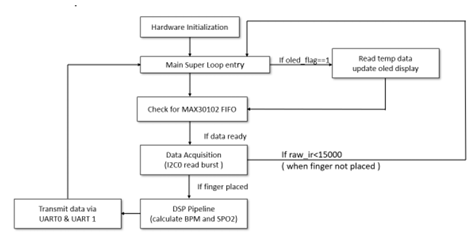
Figure 3: Firmware execution FSM
3.3 Digital Signal Processing (DSP)
Because the raw optical signals are dominated by static tissue baseline and high-frequency noise, the raw sensor data is passed through a two-stage filter pipeline:
• DC Removal Filter (IIR): Tracks and subtracts the massive DC baseline.
• Moving Average Filter (4 tap FIR): Smooths out high-frequency electrical noise.

Figure 4: DSP Pipeline
IV.MATHEMATICAL IMPLEMENTATION
4.1 Body Temperature
The MLX90614 returns temperature data as an integer. The firmware reads the raw 15-bit word from the sensor and applies a custom mathematical conversion in C to calculate Celsius: Temp = (RawData/5) − 273.1.
4.2 Heart Rate (BPM) Calculation
Following the DSP filtering, the signal is fed into the Beat Detector. To prevent false triggers on noise or the dicrotic notch, the system utilizes dynamic thresholding. The trigger line is calculated as:
![]()
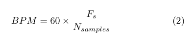
The algorithm calculates the number of samples between two threshold crossings in the 10ms sample time and estimates BPM using:
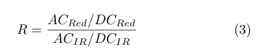
4.3 Blood Oxygen (SpO2) Calculation
SpO2 relies on calculating the Ratio of Ratios, which normalizes the AC heartbeat pulse against the DC tissue baseline according to the Beer-Lambert law:
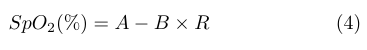
Finally, an empirical calibration formula converts the R value into a clinical percentage:
V.TELEMETRY INTERFACES
The dual-telemetry architecture successfully bridges the embedded hardware with high-level user interfaces.
5.1 PC Dashboard
Processed dual-channel data is streamed over UART0 at 115200 baud to a custom Python GUI, enabling real-time waveform inspection
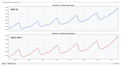
Figure 5: PC Live Visualization dashboard rendering IR and Red waveforms
5.2 Mobile Application
Simultaneously, UART1 transmits the calculated SpO2 and BPM metrics via the HC-05 module to an Android mobile app, fulfilling the wireless monitoring objective.
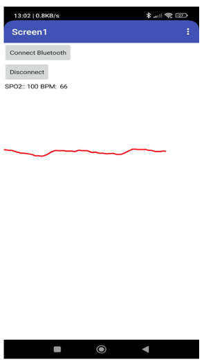
Figure 6: Mobile App interface connected via Bluetooth
VI.FUTURE IMPROVEMENTS
To evolve this prototype into a production-ready medical IoT device, several upgrades are proposed:
• Replace the HC-05 Bluetooth module with an ESP32 or Wi-Fi SoC for direct Cloud database logging for remote access.
• Implement lightweight Machine Learning anomaly detection directly on the microcontroller to automatically flag irregular heartbeats (arrhythmias) or predict fever trends rather than just streaming raw number.
VII.CONCLUSION
The project successfully implemented a health monitoring system capable of measuring BPM, SpO2, and temperature. By leveraging efficient IIR and FIR filters, dynamic thresholding, and a non-blocking bare-metal FSM architecture, the TM4C123GXL microcontroller successfully extracts accurate clinical data and seamlessly broadcasts it across multiple telemetry channels simultaneously.
REFERENCES
[1] S. Shin, H. S. Lee, J. Chung, and H. U. Lee, “Adaptive threshold method for the peak detection of photoplethysmographic waveform,” Computers in Biology and Medicine, vol. 39, no. 12, pp. 1145–1152, 2009. Available: https://www.sciencedirect.com/science/article/abs/pii/S0010482509001826
[2] Maxim Integrated (Analog Devices), MAX30102: High-Sensitivity Pulse Oximeter and Heart-Rate Sensor for Wearable Health Datasheet, Rev. 1, 2018.
[3] Melexis, MLX90614 Family: Single and Dual Zone Infra Red Thermometer in TO-39 Datasheet, Rev. 13,2019.
[4] Texas Instruments, Tiva™ TM4C123GH6PM Microcontroller Data Sheet, Literature Number: SPMS376E,2014.
[5] HC-05 Embedded Bluetooth Serial Communication Module AT Command Set. ITead Studio, 2010.
Recent Comments