
ABSTRACT
The efficiency of photovoltaic cells is highly dependent on the angle of incidence of sunlight. This report details the design and implementation of an autonomous, dual axis solar tracking system powered by an ARM Cortex-M4 microcontroller. By integrating a four-quadrant photo-sensor array, highly calibrated servo actuators, and a Real-Time Clock (RTC) for intelligent day/night state management, this system maximizes energy harvest while minimizing the power drain of the tracking motors. Furthermore, the system implements a dynamic UART telemetry interface for real-time algorithmic tuning without requiring firmware recompilation.
Index Terms—Embedded Systems, TM4C123G, Solar Tracking, PWM, Real-Time Clock, I2C, ADC
I.INTRODUCTION
The global shift towards renewable energy has made solar power a critical focus of modern engineering. However, fixed solar panels only operate at peak efficiency for a small window of the day when the sun is directly overhead. A Dual-Axis Solar Tracker solves this problem by continuously aligning the solar panel perpendicular to the sun’s rays across both the horizontal (azimuth/pan) and vertical (elevation/tilt) axes.
This project leverages bare-metal C programming on the TI Tiva C Series TM4C123GH6PM microcontroller to create a robust, time-aware tracking state machine.
II.PROBLEM STATEMENT
Static solar panels suffer from significant energy yield losses during the early morning, late afternoon, and seasonal shifts in the sun’s trajectory. While basic single or dual-axis trackers exist, they introduce their own set of inefficiencies:
• Sensor Jitter: Basic trackers overreact to minor light variations, shadows, or passing clouds, causing the motors to constantly “hunt”. This continuous motor movement consumes more power than the tracking saves.
• Night time Energy Waste: Standard Light Dependent Resistor (LDR) trackers often get confused at sunset, attempting to track streetlights or draining battery power while searching for a light source in the dark.
• Inflexibility to Environmental Changes: Real-world solar installations exist in dynamic environments where the gradual growth of nearby vegetation alters shadow profiles and introduces new physical obstacles. Systems relying on hardcoded firmware require a complete recompilation just to adjust physical motor constraints to avoid these growing plants, making them impractical for long term deployment.
III.PROPOSED SOLUTION
To address these inefficiencies, this project proposes an intelligent, state-driven dual-axis tracker with the following features:
• Adjustable Dead band Algorithm: The software implements a configurable threshold (deadband). Motors only engage when the light differential across the sensor array exceeds this threshold.
• Time-Aware “Night Mode”: An integrated DS1307 RTC continuously tracks the time. At a configurable sunset hour, the system autonomously disables auto-tracking, parks the panel facing East, and lays it flat to await sunrise.
• Dynamic UART Telemetry & Control: A fully developed command-line interface allows operators to dynamically tune the dead band, step size, sensor polling delays, servo physical limits, and system time.
• Manual Override: A 3×3 matrix keypad allows human operators to manually position the panel.
IV.SYSTEM ARCHITECTURE
The system is built on an asynchronous super-loop architecture. A global SysTick interrupt increments a millisecond counter, creating a stable time-base. The main loop polls this counter to execute tasks asynchronously: reading sensors every 25ms, reading the RTC every 500ms, and checking the UART buffer. This ensures that slow I2C reads or incoming UART commands never block the motors from moving smoothly.
V.HARDWARE AND SOFTWARE STACKS
A. Hardware Components
The physical implementation of the tracker relies on a combination of processing, sensing, and actuation components:
• Microcontroller: TI Tiva C Series TM4C123GH6PM.This ARM Cortex-M4F board serves as the central processing unit, handling real-time logic, analog signal conversion, and precise timing control.
• Sensors & Prototyping Circuitry: The optical tracking array consists of four Light Dependent Resistors (LDRs). To create measurable analog signals, these LDRs are configured in series with four 15kΩ fixed resistors on a central prototyping breadboard to form voltage dividers. The microcontroller’s ADC channels sample the voltage directly from the central junction of these dividers. A Mini Epoxy Solar Panel (62×42 mm) is mounted on the array, featuring a 12kΩ load resistor placed across its output terminals to facilitate accurate real-time energy telemetry. A cross is mounted between the LDRs to exaggerate the shadows falling on them.
• Actuation & Mechanics: Mechanical movement is driven by two SG90 Micro Digital Servo Motors mounted to a 2-Axis Pan/Tilt Bracket, allowing for full dynamic adjustment across both azimuth and elevation planes.
• Power Isolation & Distribution: An independent 4xAA battery pack (nominally 6V) is utilized to supply power to the SG90 servos. The central breadboard acts as the primary power distribution hub, routing this 6V motor supply, the Tiva’s 3.3V logic supply, and a common shared ground (GND) to all respective subsystems. This physical isolation of the high-current motor draw from the sensitive logic circuitry completely prevents micro controller brownouts.
• Timing & I/O: A DS1307 RTC module keeps absolute time, and a 3×3 keypad allows for physical manual override commands.
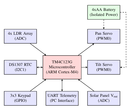
Fig. 1. High-Level Hardware Architecture Block Diagram
B. Software and Peripheral Stack
The system firmware was developed using Code Composer Studio (CCS), serving as the primary Integrated Development Environment (IDE) for writing, compiling, and flashing the embedded C code. The software architecture heavily utilizes bare-metal, memory-mapped register access to interface with the following key MCU peripherals:
• ADC (Analog-to-Digital Converter): Configured with a multi-sequencer architecture (SS2 and SS3) to rapidly process the four LDR channels and the independent solar voltage.
• PWM(Pulse Width Modulation): Programmed to generate the precise 50 Hz base frequency and microsecond accurate duty cycles required to accurately position the SG90 servos.
• I2C & UART: I2C (Master mode) handles synchronization with the DS1307 RTC, while the UART module processes asynchronous PC communications for the live telemetry stream and command-line tuning interface.
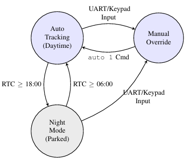
Fig. 2. Software State Machine demonstrating mode transitions based on sensor and RTC stimuli
VI.PIN MAPPING AND CONNECTIONS
The hardware connections were carefully distributed across the microcontroller ports to avoid peripheral conflicts, as detailed in Table I.
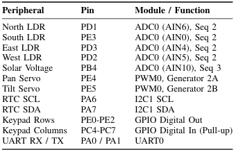
TABLE I: SYSTEM PINOUT MAPPING
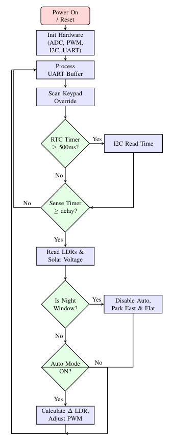
Fig. 3. Algorithmic flowchart of the asynchronous super-loop demonstrating peripheral polling and motor control execution
VII.CALCULATIONS AND CONTROL LOGIC
A. PWM Servo Calculation
Standard servos require a 50 Hz control signal (a 20 ms period). The TM4C123G runs at an internal clock speed of 16 MHz. To generate this, a PWM clock divider of 64 is utilized:
![]()
This results in a single tick duration of 4 µs. To achieve a 20ms period, the load register is calculated as:
![]()
Duty cycles are linearly mapped. A 0.5 ms pulse (0 degrees) maps to 125 ticks, while a 2.5 ms pulse (180 degrees) maps to 625 ticks.
B. ADC Voltage Translation
The internal ADC has a 12-bit resolution (0 to 4095) referenced to 3.3V. To convert the raw ADC value to millivolts dynamically without utilizing floating-point arithmetic (which is computationally expensive), the following scalar relation is used:
![]()
VIII.EMPIRICAL TESTING AND TUNING
During hardware integration, an “Electronic Endpoint” collision was observed wherein the servos emitted an audible buzzing sound near their maximum limits due to mismatched theoretical pulse widths and physical gear limits.
The integrated UART tuning suite allowed for live calibration. The hardware endpoints were dynamically tuned (e.g., modifying pan_0_ticks) and logical software constraints (pan_min = 20, tilt_max = 135) were enforced in real-time. This successfully eliminated mechanical strain with out requiring a firmware re-flash.
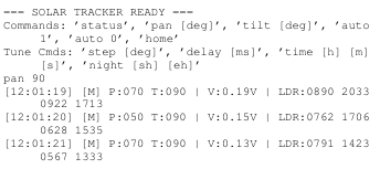
To demonstrate the telemetry stream, the following is a direct capture from the UART terminal during a transition from Auto to Manual mode:
IX.POWER MANAGEMENT ANALYSIS
The implementation of the dead band variable serves as an algorithmic low-pass filter. By requiring a light differential greater than 400 ADC units before triggering a motor movement, the system ignores micro-shadows and prevents the servo motors from continuously drawing stall-current.
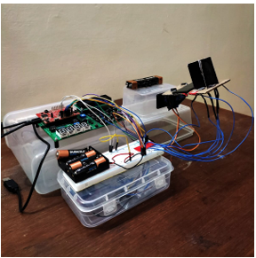
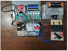
Fig. 4. Fully integrated solar tracking system: Breadboard control circuitry and pan-and-tilt mechanical assembly (top and isometric views)
Additionally, the dynamic sense_delay parameter allows operators to throttle the sensor polling rate. By increasing the delay between ADC conversions, the system reduces the number of samples processed per second, minimizing active CPU cycles and further preventing rapid, power-draining motor micro-adjustments. Furthermore, parking the system in “NightMode” completely suspends the PWM motor adjustments for
approximately 12 hours a day, drastically improving the net positive energy generation of the tracking system.
X.FUTURE WORK
While the current system is highly autonomous, future iterations could include:
1) Software Low-Pass Averaging: Implementing a circular buffer to average the last 10 LDR readings, eliminating tracking errors caused by fast-moving anomalies (e.g., birds or brief shadows).
2) Astronomical Ephemeris Tracking: Utilizing the DS1307 RTC’s exact date to calculate the mathematical position of the sun using GPS coordinates, acting as a failsafe on heavily overcast days.
3) Anemometer Integration: Integrating a wind speed sensor to automatically force the panel into a completely flat, aerodynamic parking state (0-degree tilt) during severe storms to prevent mechanical damage.
XI.CONCLUSION
This project successfully demonstrates a highly efficient, autonomous dual-axis solar tracker. By strictly integrating diverse embedded concepts, including I2C communication, multi-sequencer Analog-to-Digital conversion, Hardware PWM, and asynchronous UART parsing, the resulting architecture acts as a robust state machine. It transcends basic light-following by incorporating self-regulating algorithms that avoid the pitfalls of parasitic power drain and offers a dynamic interface for real-time engineering calibration.
REFERENCES
[1] Embedded Systems Lab, IISc, Embedded Systems Design-I (ESD-I).Available: https://labs.dese.iisc.ac.in/embeddedlab/esd-i/.
[2] Tower Pro, SG90 9 g Micro Servo Data Sheet.
Recent Comments