
Introduction
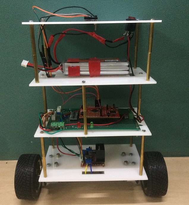
The project aims at stabilizing a 2 wheel Robot. The robot should be stable against the minor external disturbances and should be able to maintain its balance. In this project, we have designed a model of self balancing robot using the PID(Proportional, Integral, Derivative) Algorithm. The self-balancing robot is essentially an inverted pendulum. It can be balanced better if the center of mass is higher relative to the wheel axles. A higher center of mass means a higher mass moment of inertia, which corresponds to lower angular acceleration (slower fall). This is why the battery is placed on top.
Components Required
1. Tiva C series : TM4C123G Launchpad
2. MPU-6050 Six-Axis (Gyro + Accelerometer) MEMS MotionTracking Devices
3. DC motors
4. L298 H-Bridge motor driver
5. Lithium ion polymer Battery
How Does Balancing Work?
To keep the robot balanced, the motors must counteract the robot falling. This action requires feedback and correcting elements. The feedback element is the MPU6050 gyroscope + accelerometer, which gives both acceleration and rotation in all three axes. The Tiva Board uses this to know the current orientation of the robot. The correcting element is the motor and wheel combination.
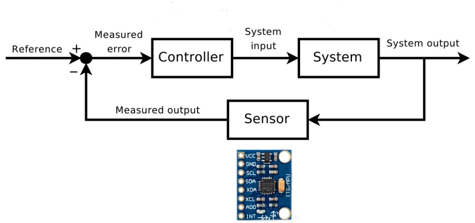
Block Diagram
MPU-6050 IMU Sensor
In order for the robot to be able to keep its balance, it requires sensors that allow it to measure its tilt accurately and at a high measurment rate. For this, we chose the MPU-6050, an IMU that combines a 3-axis gyroscope and a 3-axis accelerometer with an integrated circuit. It has a digital interface and communicates with a host microprocessor via the I2C bus. IMU measures data and store it in its internal registers. To retrieve the measurements, simply read the registers corresponding to the data you care about. Each accelerometer and gyroscope measurement comes as an integer in a set of two bytes, an upper byte and a lower byte. Concatenate the two in order to get the full piece of data.
Angle measurement: For this project, we need 3 axes of accelerometer data and one axis of gyroscope data. We read these values once every 20ms, and ran them through the complementary filter to fuse them and derive an accurate and low-latency tilt measurement. This tilt measurment is what is fed into the PID controller to balance the robot.
Need of filter
When looking for the best way to make use of a IMU-sensor, thus combining the accelerometer and gyroscope data, Kalman filter can be used to predict the exact position. But very complex to implement—another solution is complementary filter.
The problem with accelerometers: an accelerometer measures all forces that are working on the object, it will also see a lot more than just the gravity vector. Every small force working on the object will disturb our measurement completely. The accelerometer data is reliable only on the long term.
The problem with gyroscopes: it is very easy to obtain an accurate measurement that is not susceptible to external forces But the problem is because of the integration over time, the measurement has the tendency to drift, not returning to zero when the system went back to its original position. The gyroscope data is reliable only on the short term, as it starts to drift on the long term.
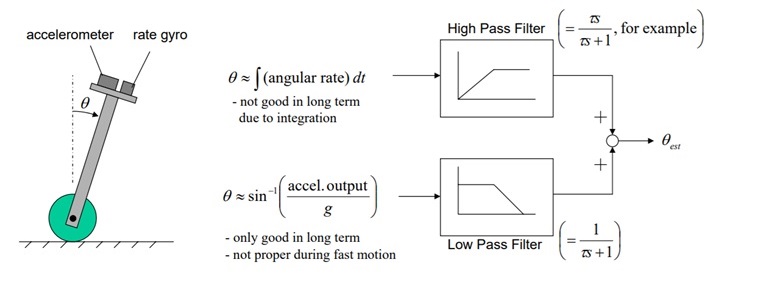
Complementary filter
The complementary filter gives us a “best of both worlds” kind of deal. On the short term, we use the data from the gyroscope, because it is very precise and not susceptible to external forces. On the long term, we use the data from the accelerometer, as it does not drift. In it’s most simple form, the filter looks as follows:
![]()
The gyroscope data is integrated every timestep with the current angle value.
PID Controller
To keep the position of the Robot intact, we need the PID controller. PID provides correction between the desired value (or input) and the actual value (or output). The difference between the input and the output is called “error”. The PID controller reduces the error to the smallest value possible by continually adjusting the output. In our case, the input (which is the desired tilt, in degrees) is set by software. The MPU6050 reads the current tilt of the robot and feeds it to the PID algorithm, which performs calculations to control the motor and keep the robot in the upright position. PID requires that the gains Kp, Ki, and Kd values be “tuned” to optimal values. Procedure to tune these gains manually.
  1. Make Kp, Ki, and Kd equal to zero.
  2. Adjust Kp. Too little Kp will make the robot fall over, because there's not enough correction. Too much Kp will make the robot go back and forth wildly. A good enough Kp will
     make the robot go slightly back and forth (or oscillate a little).
  3. Once the Kp is set, adjust Kd. A good Kd value will lessen the oscillations until the robot is almost steady. Also, the right amount
     of Kd will keep the robot standing, even if pushed.
  4. Lastly, set the Ki. The robot will oscillate when turned on, even if the Kp and Kd are set, but will stabilize in time. The correct Ki
     value will shorten the time it takes for the robot to stabilize.
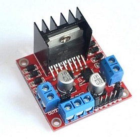
L298 Dual H-Bridge Motor Drivers
We used two motors that were connected to a dual H-bridge motor driver.The motor driver comes with a heat sink which was very important considering the large current draw of the motors, and the large amount of excess heat.
Conclusion
Current Bot will balance itself for some time and it will tend to fall on either side after some time. With good mechanical structure and fast driving motors, Bot balancing mechanism can be efficiently done.
Source Code
https://github.com/FaruqMulla/Self-Balancing-Bot
References
1. http://www.ti.com/lit/pdf/spmu296
2. https://www.invensense.com/wp-content/uploads/2015/02/MPU-6000-Register-Map1.pdf
3. https://www.invensense.com/wp-content/uploads/2015/02/MPU-6000-Datasheet1.pdf
Recent Comments