
ABSTRACT
This project presents the design and implementation of a self-balancing robot integrated with gesture-based and line-following control mechanisms. The system uses a Tiva TM4C123 microcontroller to interface with an Inertial Measurement Unit (IMU), stepper motors, and Bluetooth modules, enabling real-time feedback and control. A PID controller processes sensor data to maintain balance dynamically.
The robot supports three modes of operation: manual control via keypad, gesture control using an MPU6050 sensor, and autonomous line following using IR sensors. This multi-modal control system demonstrates the effective integration of embedded systems, control algorithms, and wireless communication in robotics, offering a robust and user-friendly platform for both educational and prototyping applications.
I INTRODUCTION
Self-balancing robots are an important area of research and experimentation in modern robotics, demonstrating the integration of control theory, real-time sensor processing, and embedded systems. These robots mimic the behavior of an inverted pendulum and require continuous adjustments to maintain their vertical position, providing an ideal platform to explore dynamic system stabilization. In this project, the self-balancing robot is enhanced with gesture-based control and line-following functionality, allowing for both manual and autonomous operation modes. The robot uses stepper motors to achieve high-precision actuation, essential for maintaining balance and executing smooth movements. The central processing unit of the system is the Tiva TM4C123 microcontroller, which collects data from various sensors, executes control algorithms, and manages motor drivers. The robot maintains balance through an IMU that provides real-time orientation and acceleration data to a PID control algorithm, which adjusts the motor output accordingly. Gesture control is implemented via a Bluetooth-enabled accelerometer- based controller, translating hand motions into robot movements. For path navigation, infrared sensors detect and follow lines on the ground, enabling the robot to autonomously follow a predefined route. By integrating real-time balance control with intuitive human input and autonomous navigation, this project demonstrates a versatile robotic platform suitable for education, prototyping, and intelligent automation applications.
II PID CONTROLLER
To maintain balance, the robot implements a PID (Proportional−Integral−Derivative) controller that continuously adjusts the continuously adjusts the stepper motor outputs based on the robot’s tilt angle. This angle is computed by fusing sensor data from the accelerometer and gyroscope, which are part of the Inertial Measurement Unit (IMU). The accelerometer provides an absolute angle estimate based
on the Z-axis register, while the gyroscope offers angular velocity, which helps predict fast changes in orientation.
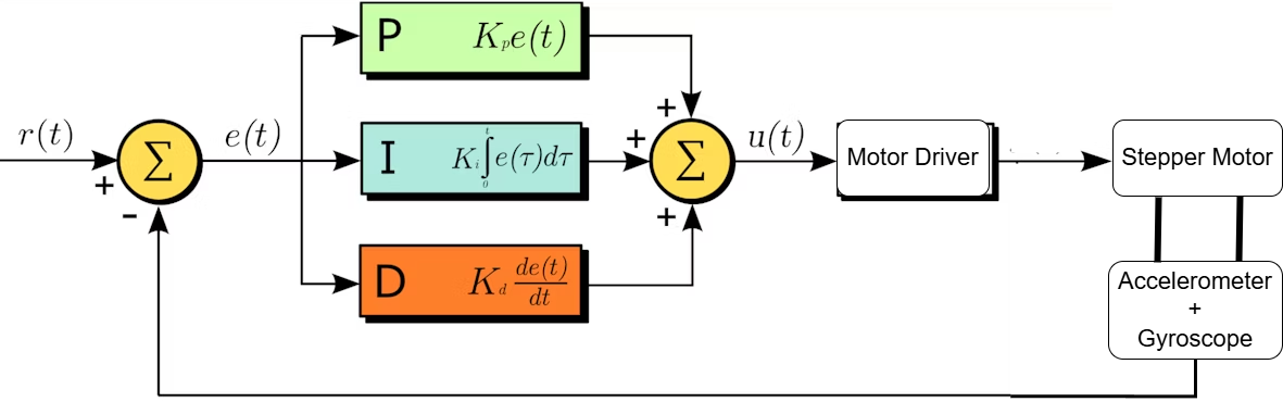
Figure 1: PID Controller Block Diagram
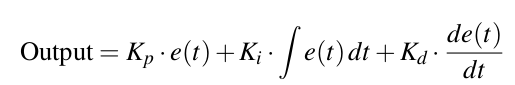
e(t) = error = desired angle – measured angle
Kp, Ki, Kd = PID constants
The output of the PID controller determines the step rate and direction of the stepper motors. Faster response is required when the tilt is large or changing quickly, while minimal correction is applied when the robot is near equilibrium. The tuned PID constants Kp, Ki, Kd are critical and were determined empirically through trial-and-error to achieve a stable response with minimal overshoot and oscillation.
By continuously updating motor commands based on the PID output, the robot maintains its upright position dynamically in real-time, compensating for small disturbances and shifts in weight.
III BLUETOOTH REMOTE CONTROL
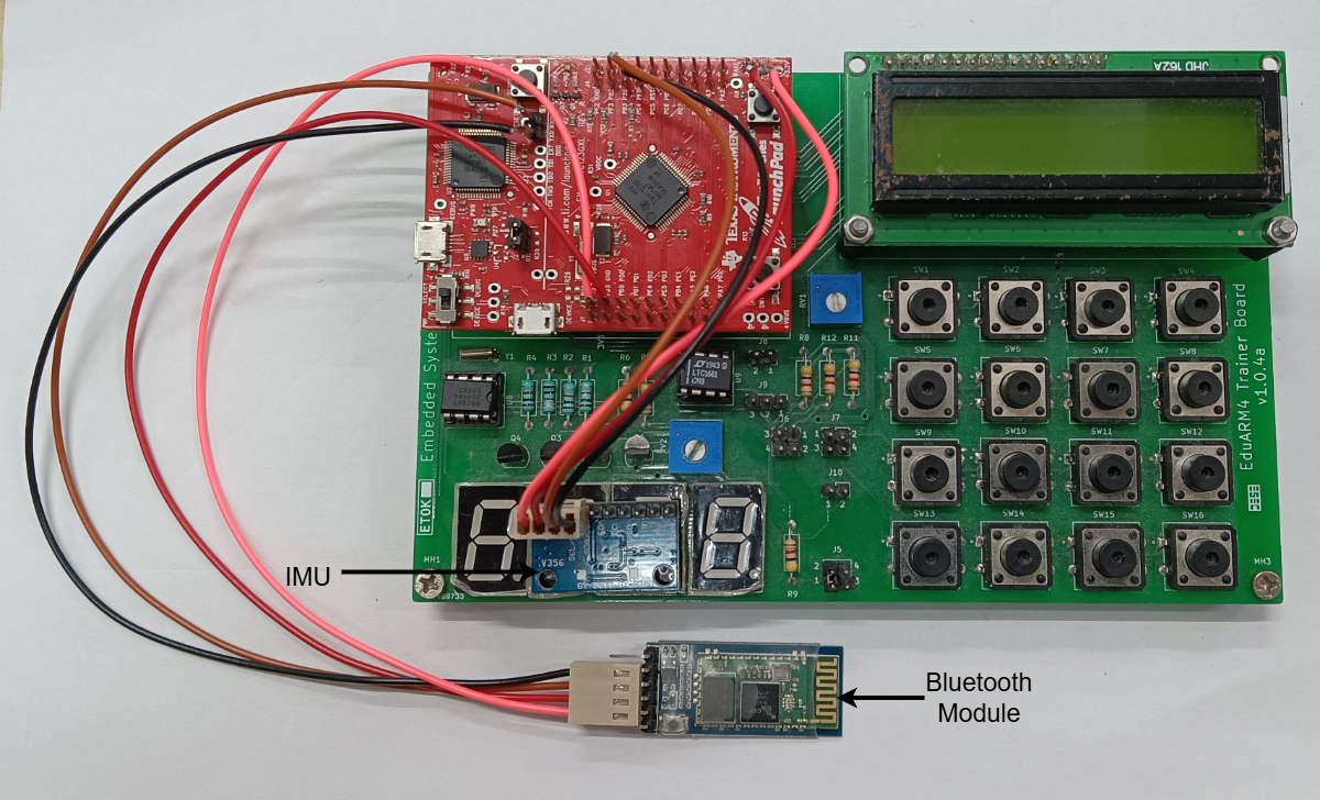
Figure 2: Bluetooth Remote
IV BLUETOOTH REMOTE CONTROL
The Bluetooth remote system enables wireless manual and gesture-based control of the self-balancing robot. It operates in three distinct modes-Keypad Mode, Gesture Mode, and Line Following Mode-which can be selected using an onboard switch connected to the Tiva TM4C123 microcontroller.
4.1 Mode Selection via Tiva Switch
The mode of operation is determined by reading the state of a physical switch connected to a GPIO pin on the Tiva board. Based on the switch’s position, the microcontroller activates one of the following modes:
• Mode 0 − Keypad Control
• Mode 1 − Gesture Control
• Mode 2 − Line Following
This modular approach allows for flexible interaction without reprogramming the robot.
4.2 Keypad Mode (Manual Control)
In this mode, a 4×4 matrix keypad is used to send directional commands wirelessly over Bluetooth. Each key corresponds to a specific movement:
• 8 → Forward
• 5 → Backward
• 6 → Turn Clockwise
• 4 → Turn Anti-Clockwise
The keypad is connected to a Bluetooth-enabled controller that transmits ASCII commands to the robot. The Tiva board receives and decodes these commands via UART and adjusts the stepper motor behavior accordingly.
4.3 Gesture Mode (Accelerometer Control)
Gesture control enables the robot to respond to tilts and motions of a handheld controller containing an accelerometer sensor (such as MPU6050). The controller continuously monitors acceleration along the X and Y axes. When tilt beyond a set threshold value is detected, it transmits movement commands:
• Tilt forward → Move Forward
• Tilt backward → Move Backward
• Tilt left → Turn Anti-Clockwise
• Tilt right → Turn Clockwise
A dead zone is implemented to prevent small hand tremors from triggering commands. This mode offers intuitive control by mimicking the user’s hand motion.
4.4 Bluetooth Communication
All commands from the keypad or gesture controller are transmitted via a Bluetooth module (such as HC-05 or HC-06) interfaced with the Tiva microcontroller through UART. The Tiva firmware uses interrupt-driven or polling-based UART communication to receive and parse commands in real time, ensuring low-latency response. This remote control setup not only enhances user interaction but also demonstrates robust integration of input interfaces with embedded systems and wireless communication. The seamless switch between gesture, manual, and autonomous modes reflects a well-designed, user-centric robotics platform.
V LINE FOLLOWER
This project involves the design and implementation of a basic line follower using a single infrared (IR) sensor on both sides of the wheels. The IR sensor detects the contrast between a black line and a white background. The microcontroller processes this signal to control the movement of the robot, ensuring it follows the path.
IR Sensor Block:
The process starts by reading data from two IR sensors placed on the left (IR L) and right (IR R) sides of the robot.
Sensor Condition Checks:
If IR L detects the line (typically a black surface), it triggers one logic branch.
If IR R detects the line, it triggers another.
Motor Control Based on PID:
If IR L detects the line, and PID > 0 (meaning error is pos-itive), the robot corrects itself by rotating right (clockwise) to align back.
If IR R detects the line, and PID > 0, the robot rotates left (anti-clockwise) to realign.
If Both Sensors Don’t Detect or Both Detect:
If neither sensor detects a strong signal or both detect the same,the robot moves forward, assuming it’s properly aligned.
Motor Actions:
Clockwise (CW) and Anti-Clockwise (ACW) refer to the turning direction of the motors to adjust the robot’s path.
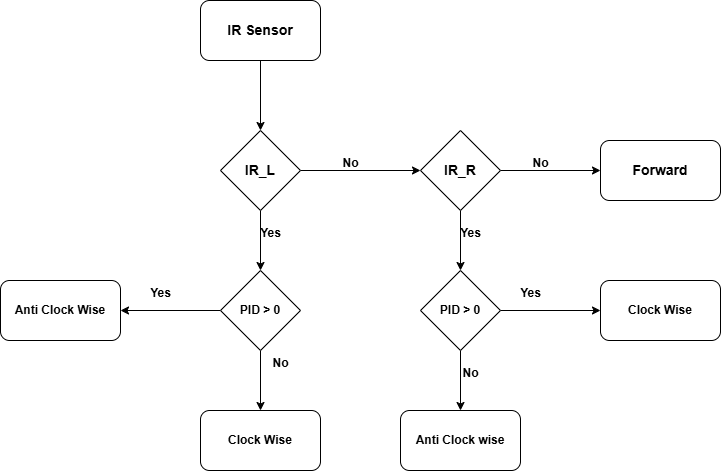
Figure 3: Flowchart of Line Follower
VI GESTURE CONTROL
This project demonstrates controlling a self-balancing system using gestures via the MPU6050 sensor. The MPU6050, which combines an accelerometer and gyroscope, captures real-time data on the device’s tilt and motion. Gesture recognition algorithmsprocess this data, allowing specific hand or body motions to control the balancing system. By mapping gestures to parameters like tilt angle or speed, the system adjusts its orientation to maintain balance. This approach provides an intuitive and hands-free way of controlling a self-balancing device.
MPU6050 Sensor Block:
This system uses the MPU6050 sensor to read the X and Y-axis accelerations.
X-axis Based Motion:
If acceleration along X (accX ) is greater than threshold T , the robot moves forward.
If accX < T , the robot moves backward.
Y-axis Based Rotation:
If acceleration along Y (accY ) is greater than threshold T , the robot rotates clockwise.
If accY < T , the robot rotates anti-clockwise.
Idle Condition:
If neither X nor Y acceleration crosses the threshold significantly, the robot remains stationary (stand still).
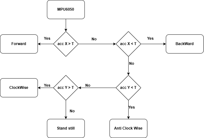
Figure 4: Flowchart of MPU6050-based Gesture Control
VII HARDWARE
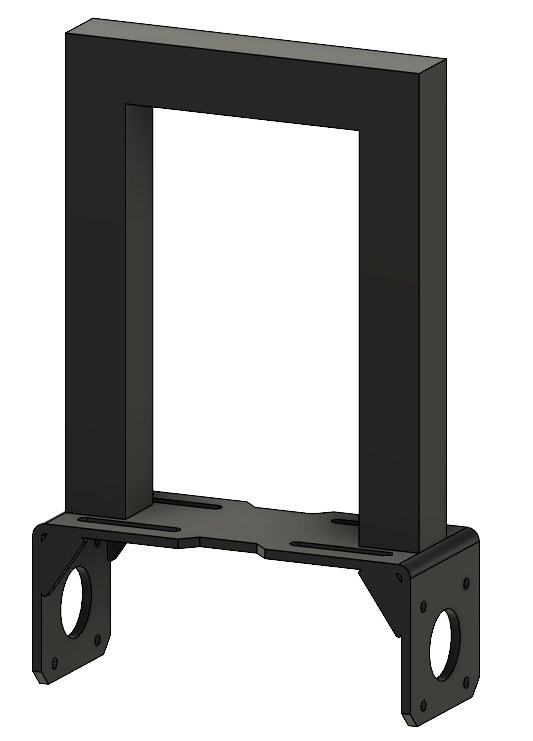
Figure 5: 3D Model of Frame
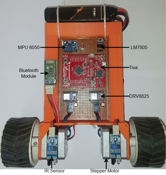
Figure 6: Robot
The self-balancing robot consists of multiple integrated hardware components, each playing a crucial role in ensuring stability, mobility, and control. The system is powered by a 12V battery, regulated down to 5V using a voltage regulator circuit to safely power all onboard electronics, including the microcontroller, sensors, and communication modules.
7.1 Microcontroller
The Tiva TM4C123GH6PM microcontroller serves as the central processing unit. It collects sensor data, executes control algo-rithms, and interfaces with motor drivers and communication modules.
7.2 Inertial Measurement Unit (IMU)
An IMU module (typically an MPU6050) is mounted at the top of the robot to provide accurate measurement of the tilt angle. Its elevated placement minimizes vibrations and allows for better isolation of inertial changes, enhancing the stability of the PID-based balance control.
7.3 Voltage Regulation
A 5V voltage regulator is used to step down the 12V input from the battery to a stable 5V required for the Tiva board, IMU, Bluetooth module, IR sensors, and other peripherals. This ensures safe and consistent operation of the electronic components.
7.4 Infrared (IR) Sensors
A set of infrared line sensors is placed near the stepper motors at the bottom of the robot to detect black lines on the ground. These sensors provide real-time feedback for the line-following algorithm, enabling the robot to adjust its path during autonomous navigation.
7.5 Stepper Motors and Drivers
Two bipolar stepper motors are used for locomotion, providing precise angular control necessary for balancing and movement. The motors are driven by stepper drivers capable of receiving pulse inputs from the microcontroller and adjusting motor steps accordingly. This hardware configuration enables robust balance control, user interaction, and autonomous path following in a compact
and modular platform.
VIII FUTURE S COPE
• Obstacle Avoidance: Integration of ultrasonic or LiDAR sensors can enable the robot to detect and avoid obstacles while navigating autonomously.
• Speed Optimization: Adaptive control techniques can be implemented to dynamically adjust speed based on terrain or user input for improved performance.
• Machine Learning Integration: Implementing machine learning algorithms could enhance gesture recognition and enable autonomous decision-making in complex environments.
• Camera-Based Vision: Incorporating a camera module with image processing capabilities would allow for advanced nav-igation such as object detection or visual line following.
• Mobile App Control: Development of a mobile application for controlling and monitoring the robot can improve usability and extend the interface beyond physical remotes.
• Battery Monitoring System: Adding real-time power management features will enhance reliability during extended oper-ation.
IX CONCLUSION
The development of a self-balancing robot with integrated gesture and line-following control demonstrates a successful im- plementation of real-time control, sensor fusion, and human-machine interaction. By using stepper motors for precise movement and the Tiva TM4C123 microcontroller for efficient control logic execution, the robot achieves reliable balance and responsive
navigation. The gesture control system, enabled via a Bluetooth-connected accelerometer, provides an intuitive way for users to interact with the robot, while the line-following feature enables autonomous path tracking using infrared sensors. Overall, the project showcases the practical application of embedded systems, control algorithms, and wireless communication in robotics. It lays a solid foundation for future enhancements such as obstacle avoidance, speed optimization, and machine learning-based decision-making, making it a valuable platform for both educational and research purposes.
Recent Comments