
GPIO – Set up the type, event, and mask of the interrupts for each port
We can configure the GPIOIS, GPIOIBE, GPIOEV, and GPIOIM registers to set up the type, event, and mask of the interrupts for each port if interrupts are used for the port.
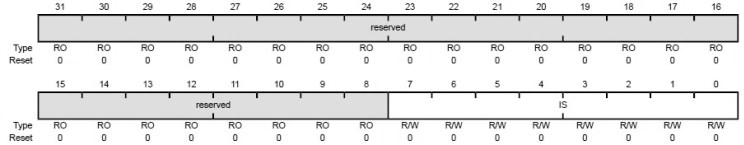
GPIO Interrupt Sense (GPIOIS)
The GPIOIS register is the interrupt sense register. Setting a bit in the GPIOIS register configures the corresponding pin to detect levels, while clearing a bit configures the corresponding pin to detect edges. All bits are cleared by a reset.
| Bit/Field | Name | Description |
|---|---|---|
| 7:0 | IS | GPIO Interrupt Sense 0: The edge on the corresponding pin is detected (edge-sensitive). 1: The level on the corresponding pin is detected (level-sensitive). |
| 31:8 | Reserved | Software should not rely on the value of a reserved bit. |
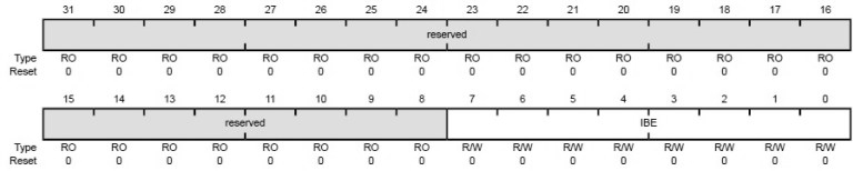
GPIO Interrupt Both Edges (GPIOIBE)
The GPIOIBE register allows both edges to cause interrupts. When the corresponding bit in the GPIO Interrupt Sense (GPIOIS) register is set to detect edges, setting a bit in the GPIOIBE register configures the corresponding pin to detect both rising and falling edges, regardless of the corresponding bit in the GPIO Interrupt Event (GPIOIEV) register. Clearing a bit configures the pin to be controlled by the GPIOIEV register. All bits are cleared by a reset.
| Bit/Field | Name | Description |
|---|---|---|
| 7:0 | IBE | GPIO Interrupt Both Edges 0: Interrupt generation is controlled by the GPIO Interrupt Event (GPIOIEV). 1: Both edges on the corresponding pin trigger an interrupt. |
| 31:8 | Reserved | Software should not rely on the value of a reserved bit. |
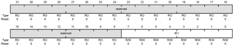
GPIO Interrupt Event (GPIOIEV)
The GPIOIEV register is the interrupt event register. Setting a bit in the GPIOIEV register configures the corresponding pin to detect rising edges or high levels, depending on the corresponding bit value in the GPIO Interrupt Sense (GPIOIS) register. Clearing a bit configures the pin to detect falling edges or low levels, depending on the corresponding bit value in the GPIOIS register. All bits are cleared by a reset.
| Bit/Field | Name | Description |
|---|---|---|
| 7:0 | IEV | GPIO Interrupt Event 0: A falling edge or a Low level on the corresponding pin triggers an interrupt. 1: A rising edge or a High level on the corresponding pin triggers an interrupt. |
| 31:8 | Reserved | Software should not rely on the value of a reserved bit. |
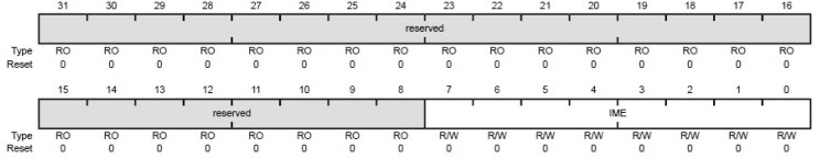
GPIO Interrupt Mask (GPIOIM)
The GPIOIM register is the interrupt mask register. Setting a bit in the GPIOIM register allows interrupts that are generated by the corresponding pin to be sent to the interrupt controller on the combined interrupt signal. Clearing a bit prevents an interrupt on the corresponding pin from being sent to the interrupt controller. All bits are cleared by a reset.
| Bit/Field | Name | Description |
|---|---|---|
| 7:0 | IME | GPIO Interrupt Mask Enable 0: The interrupt from the corresponding pin is masked. 1: The interrupt from the corresponding pin is sent to the interrupt controller. |
| 31:8 | Reserved | Software should not rely on the value of a reserved bit. |
Note:
To prevent false interrupts, the following steps should be taken when re-configuring GPIO edge and interrupt sense registers:
- Mask the corresponding port by clearing the IME field in the GPIOIM register.
- Configure the IS field in the GPIOIS register and the IBE field in the GPIOIBE register.
- Clear the GPIORIS register.
- Unmask the port by setting the IME field in the GPIOIM register.
Recent Comments