
GPIO – Set up the direction for each pin on the GPIO
Set up the direction for each pin on the GPIO port by programming the GPIODIR register. Generally every microcontroller has minimum of two registers associated with each of I/O port – Data Register and Direction Register. The Direction register is used to make the pin either input or output. After the Direction register is properly configured, then we use the Data register to actually write to the pin or read data from the pin. It is the Direction register (when configured as output) that allows the information written to the Data register to be driven to the pins of CPU. The same way, it is the Direction register (when configured as input) that allows the signal present at the CPU pin to be brought into the Data register.
GPIO Data Direction Register (GPIODIR)
This register tells the microcontroller that which pin is going to be the input (by making the bit 0) and which is going to be output (by making the bit 1) to their respective field in the DIR register.
It’s 8 bit wide. We are going to use PF0-PF5 so we will move 0b00001110 (0x0E) to the DIR register.
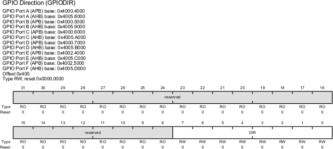
| Bit/Field | Name | Description |
|---|---|---|
| 7:0 | DIR | GPIO Data Direction 0: Corresponding pin is an input. 1: Corresponding pins is an output. |
| 31:8 | Reserved | Software should not rely on the value of a reserved bit. |
- Each of the Direction register bit needs to be a 0 to configure the port pin as input and a 1 as output.
Recent Comments