
GPIO – Configure each pad in the port to have pull-up, pull-down, or open drain
We can configure each pad in the port to have pull-up, pull-down, or open drain function through the GPIOPUR, GPIOPDR , or GPIOODR register. Slew rate may also be configured, if needed, through the GPIOSLR register.
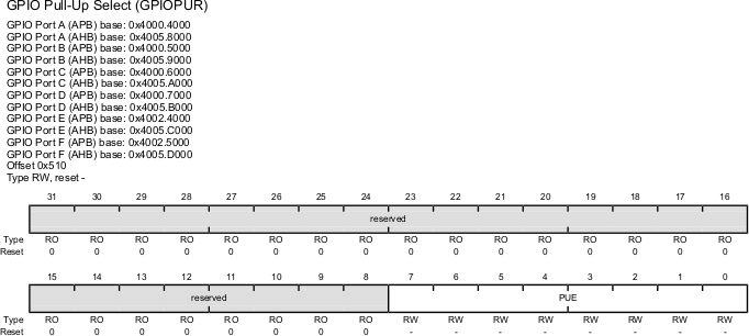
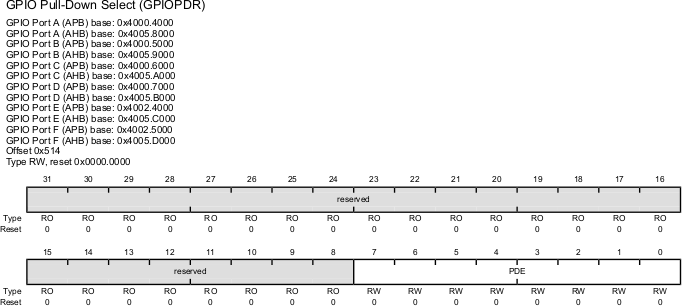
GPIO Pull-Up Select (GPIOPUR), GPIO Pull-Down Select (GPIOPDR)
- The GPIOPUR register is the pull-up control register.
- When a bit is set, a weak pull-up resistor on the corresponding GPIO signal is enabled.
- Setting a bit in GPIOPUR automatically clears the corresponding bit in the GPIO Pull-Down Select (GPIOPDR) register.
- The GPIOPDR register is the pull-down control register.
- When a bit is set, a weak pull-down resistor on the corresponding GPIO signal is enabled.
- Setting a bit in GPIOPDR automatically clears the corresponding bit in the GPIO Pull-Up Select (GPIOPUR) register.
GPIO Pull-Up Select (GPIOPUR) Register
| Bit/Field | Name | Description |
|---|---|---|
| 7:0 | PUE | Pad Weak Pull-Up Enable 0: The corresponding pin’s weak pull-up resistor is disabled. 1: The corresponding pin’s weak pull-up resistor is enabled. Setting a bit in the GPIOPDR register clears the corresponding bit inthe GPIOPUR register. The change is effective on the second clock cycle after the write if accessing GPIO via the APB memory aperture. If using AHB access, the change is effective on the next clock cycle. |
| 31:8 | Reserved | Software should not rely on the value of a reserved bit. |
GPIO Pull-Down Select (GPIOPDR) Register
| Bit/Field | Name | Description |
|---|---|---|
| 7:0 | PDE | Pad Weak Pull-Down Enable 0: The corresponding pin’s weak pull-down resistor is disabled. 1: The corresponding pin’s weak pull-down resistor is enabled. Setting a bit in the GPIOPUR register clears the corresponding bit in the GPIOPDR register. The change is effective on the second clock cycle after the write if accessing GPIO via the APB memory aperture. If using AHB access, the change is effective on the next clock cycle. |
| 31:8 | Reserved | Software should not rely on the value of a reserved bit. |
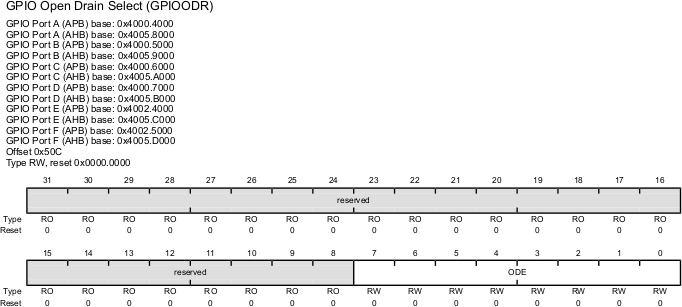
GPIO Open Drain Select (GPIOODR)
The GPIOODR register is the open drain control register. Setting a bit in this register enables the open-drain configuration of the corresponding GPIO pad. When open-drain mode is enabled, the corresponding bit should also be set in the GPIO Digital Enable (GPIODEN) register (see page 682). Corresponding bits in the drive strength and slew rate control registers (GPIODR2R, GPIODR4R, GPIODR8R, and GPIOSLR) can be set to achieve the desired fall times. The GPIO acts as an input if the corresponding bit in the GPIODIR register is cleared. If open drain is selected while the GPIO is configured as an input, the GPIO will remain an input and the open-drain selection has no effect until the GPIO is changed to an output.
| Bit/Field | Name | Description |
|---|---|---|
| 7:0 | ODE | Output Pad Open Drain Enable 0: The corresponding pin is not configured as open drain.. 1: The corresponding pin is configured as open drain. |
| 31:8 | Reserved | Software should not rely on the value of a reserved bit. To provide compatibility with future products, the value of a reserved bit should be preserved across a read-modify-write operation. |
Recent Comments