
Interfacing the LM35 to the TI Tiva TM4C123G Microcontroller
In this tutorial we will see how to interface LM35 Temperature sensor with EK-TM4C123GXL LaunchPad Board. LM35 is a well known low cost temperature sensor. It is directly calibrated in Degrees Celsius meaning that the output voltage is directly proportional to Degrees Celsius readings. Its measurement range is from -55°C to 150°C having typical accuracy(s) of 0.25°C at room temperature and 0.75°C for full range. LM35 also supports a wide range of supply voltage from 4V to 30V and is available in 4 different packages viz. TO-CAN, TO-92, SOIC and TO-220.
LM35 Pinout for TO-92 Package
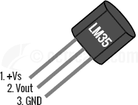
- Pin 1 (+Vs) is the positive power supply pin
- Pin 2 (VOUT) provides the output voltage linearly proportional to temperature and
- Pin 3 is for Ground.
LM35 can be configured in two ways:
- Basic Centigrade Temperature Sensor (2°C to 150°C)
- Full Range Centigrade Temperature sensor (-55°C to 150°C)
For the sake of simplicity, we will use LM35 in basic configuration. The first thing to note when interfacing LM35 with 3.3v MCUs is that LM35 has a supply voltage range of 4V to 30V. Hence, another supply of say 5V would be required to get proper readings. The second thing to note is that the output voltage has a scale factor of 10mV per Degree Centigrade and this is fixed irrespective of what supply voltage you use between 4V to 30V. Hence, the output voltage can go max up to 1.5V and as low as -55mV when configured as Full Range Centigrade Sensor.
The A/D of TI Tiva TM4C123G Microcontroller has 12-bit resolution with a maximum of 4096 steps, and the LM35 produces 10 mV for every degree of temperature change. The maximum operating temperature of the LM35 is 300 degrees F, so the highest output will be 3000 mV (3.00 V), which is below 3.3V of Vref.
When using the Basic configuration we have an output swing of ~0V(20mV) to 1.5V. So, if we use a VREF of 3.3 Volts we get a resolution of 3.3V/4096 = 0.0008V or 0.8mV since TM4C123GH6PM has a 12-bit ADC. Considering that LM35’s typical accuracy at room temperature(25°C) is 0.25°C (worst case accuracy = 0.5°C @ 25°C) and scale factor of 10mV/°C, a resolution of 3.22mV barely fits the bill. To get better resolution we can use a lower voltage reference like 1.8V or 2V. For example, using 1.8V reference we get a resolution of 1.75mV. For the interfacing example given below, we will assume a voltage reference of 3.3V which is used in our development board.
LM35 Transfer Function & Output Conversion to °C
The formula for VOUT is given as:
VOUT(mV) = 10mV/°C * T
Using the above formula, with VREF in Volts and Scale-factor in V/°C, we can compute the temperature(T) from 12-bit ADC Result as:
T = (ADC_RESULT * VREF)/4096 * 0.01 °C
Which can be simplified as,
T = (ADC_RESULT * VREF * 100)/4096 °C
So, when using VREF = 3.3V we get,
T = (ADC_RESULT * 330) / 4096 °C
Source Code is available
Interfacing LM35 Sensor – Source
-
/* Interfacing LM35 temperature sensor */ -
/* LM35 is connected to Chan0. */ -
/* -
* This program converts the analog output from an LM35 and convert it to -
* temperature in Fahrenheit. AIN0 channel is on PE3 pin. -
* Temp is sent to UART to be viewed on UART Terminal -
* -
*/ -
#include <stdint.h> -
#include <stdio.h> -
#include "inc/tm4c123gh6pm.h" -
void UART0Tx(char c);
-
void UART0_init(void);
-
void UART0_puts(char* s);
-
void delayMs(int n);
-
int main(void)
-
{ -
int temperature;
-
char buffer[18];
-
/* initialize UART0 for output */ -
UART0_init();
-
/* enable clocks */ -
SYSCTL_RCGCGPIO_R |= 0x10; /* enable clock to GPIO_PORTE */
-
SYSCTL_RCGCADC_R |= 1; /* enable clock to ADC0 */
-
/* initialize PE3 for AIN0 input */ -
GPIO_PORTE_AFSEL_R |= 8; /* enable alternate function */
-
GPIO_PORTE_DEN_R &= ~8; /* disable digital function */
-
GPIO_PORTE_AMSEL_R |= 8; /* enable analog function */
-
/* initialize ADC0 */ -
ADC0_ACTSS_R &= ~8; /* disable SS3 during configuration */
-
ADC0_EMUX_R &= ~0xF000; /* software trigger conversion */
-
ADC0_SSMUX3_R = 0; /* get input from channel 0 */
-
ADC0_SSCTL3_R |= 6; /* take one sample at a time, set flag at 1st sample */
-
ADC0_ACTSS_R |= 8; /* enable ADC0 sequencer 3 */
-
while(1) {
-
ADC0_PSSI_R |= 8; /* start a conversion sequence 3 */
-
while((ADC0_RIS_R & 0x08) == 0)
-
; /* wait for conversion to complete */
-
temperature = ((ADC0_SSFIFO3_R * 330) / 4096);
-
ADC0_ISC_R = 8; /* clear completion flag */
-
sprintf(buffer, "\r\nTemp = %dF", temperature);
-
UART0_puts(buffer);
-
delayMs(1000);
-
} -
} -
void UART0_init(void)
-
{ -
SYSCTL_RCGCUART_R |= 1; /* provide clock to UART0 */
-
SYSCTL_RCGCGPIO_R |= 0x01; /* enable clock to GPIO_PORTA */
-
/* UART0 initialization */ -
UART0_CTL_R = 0; /* disable UART0 */
-
UART0_IBRD_R = 104; /* 16MHz/16=1MHz, 1MHz/104=9600 baud rate */
-
UART0_FBRD_R = 11; /* fraction part, see Example 4-4 */
-
UART0_CC_R = 0; /* use system clock */
-
UART0_LCRH_R = 0x60; /* 8-bit, no parity, 1-stop bit, no FIFO */
-
UART0_CTL_R = 0x301; /* enable UART0, TXE, RXE */
-
/* UART0 TX0 and RX0 use PA0 and PA1. Set them up. */ -
GPIO_PORTA_DEN_R = 0x03; /* Make PA0 and PA1 as digital */
-
GPIO_PORTA_AFSEL_R = 0x03; /* Use PA0,PA1 alternate function */
-
GPIO_PORTA_PCTL_R = 0x11; /* configure PA0 and PA1 for UART */
-
} -
void UART0Tx(char c)
-
{ -
while((UART0_FR_R & 0x20) != 0); /* wait until Tx buffer not full */
-
UART0_DR_R = c; /* before giving it another byte */
-
} -
void UART0_puts(char* s)
-
{ -
while (*s != 0) /* if not end of string */
-
UART0Tx(*s++); /* send the character through UART0 */
-
} -
/* delay n milliseconds (16 MHz CPU clock) */ -
void delayMs(int n)
-
{ -
int32_t i, j;
-
for(i = 0 ; i < n; i++)
-
for(j = 0; j < 3180; j++)
-
{;} /* do nothing for 1 ms */
-
}
Recent Comments