
Inter-Integrated Circuit (I2C) Interface
The inter-integrated circuit I2C interface was proposed by Philips in the late 1980s as a means to connect external devices to the micro controller using just two wires. The SSI interface has been very popular, but it takes 3-wires for simplex and 4-wires for full duplex communication. The I2C bus is a simple two-wire bi-directional serial communication system that is intended for communication between micro controllers and their peripherals over short distances. This is typically, but not exclusively, between devices on the same printed circuit board, the limiting factor being the bus capacitance. I2C is ideal to attach low-speed peripherals to a motherboard or embedded system or anywhere that a reliable communication over a short distance is required.
I2C provides a connection oriented communication with acknowledge. I2C devices use only 2-pins for data transfer, instead of the 8 or more pins used in traditional parallel buses. These two signals are called “Serial Clock” (SCL) which synchronize the data transfer between two chips, and “Serial Data” (SDA). The interface will operate at baud rates of up to 100 kbps with maximum capacitive bus loading. The module can operate up to a baud rate of 400 kbps provided the I2C bus slew rate is less than 100ns. The maximum interconnect length and the number of devices that can be connected to the bus are limited by a maximum bus capacitance of 400pF in all instances. These parameters support the general trend that communication speed can be increased by reducing capacitance. Version 2.0 supports a high speed mode with a baud rate up to 2.4 MHz (supported by TM4C).
I2C Bus Functional Overview
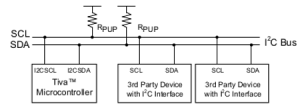
The Serial Clock Line (SCL) and the Serial Data line (SDA) are both bi-directional. Each line is open-drain, meaning a device may drive it low or let it float. A logic high occurs if all devices let the output float, and a logic low occurs when at least one device drives it low. The value of the pull-up resistor depends on the speed of the bus. 4k7 is recommended for baud rates below 100 kbps, 2k2 is recommended for standard mode, and 1kΩ is recommended for fast mode.
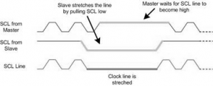
The SCL clock is used in a synchronous fashion to communicate on the bus. Even though data transfer is always initiated by a master device, both the master and the slaves have control over the data rate. The master starts a transmission by driving the clock low, but if a slave wishes to slow down the transfer, it too can drive the clock low (called clock stretching). In this way, devices on the bus will wait for all devices to finish. Both address (from Master to Slaves) and information (bi-directional) are communicated in serial fashion on SDA.
I2C Nodes
In I2C protocol, more than 100 devices can share an I2C bus. Each of these devices is called a node. Each node can operate as either master or slave. Master is a device that generate the Clock for the system, it also initiate and terminate a transmission. Slave is node that receives the clock and is addressed by the master. In I2C, both master and slave can receive or transmit data. So there are 4 modes of operation. They are:
- master transmitter,
- master receiver,
- slave transmitter and
- slave receiver.
Notice that each node can have more than one mode of operation at different times but it has only one mode of operation at the same time.
START and STOP conditions
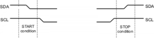
I2C is a connection oriented communication protocol, it means that each transmission is initiated by a START condition and is terminated by STOP condition. Remember that the START and STOP conditions are generated by the master.
- A High-to-Low transition on the SDA line while the SCL is High is defined as a START condition, and a
- Low-to-High transition on the SDA line while SCL is High is defined as a STOP condition.
The bus is considered busy after a START condition and free after a STOP condition.
The bus is considered busy between each pair of START and STOP conditions and no other master tries to take control of the bus when it is busy. If a master, which has the control of the bus, wishes to initiate a new transfer and does not want to release the bus before starting the new transfer, it issues a new START condition between a pair of START and STOP condition. It is called REPEATED START condition or simply RESTART condition.
Message format in I2C
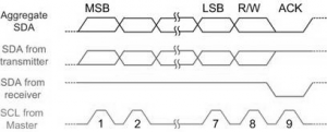
In I2C, each address or data to be transmitted must be framed in 9-bit long. The first 8-bits are put on SDA line by the transmitter and the 9th bit is the acknowledge (ACK) by the receiver or it may be NACK (negative acknowledge). Notice that the clock is always generated by the master, regardless of it being transmitter or receiver. To allow acknowledge, the transmitter releases the SDA line during the 9th clock so the receiver can pull the SDA line low to indicate an ACK. If the receiver doesn’t pull the SDA line low, it is considered as NACK.
In I2C, each byte may contain either address or data. Also notice that:
START condition + slave address byte + one or more data byte + STOP condition
together form a complete data transfer.
Address Byte Format
All address bytes transmitted on the I2C bus are nine bits long. It consists of seven address bits, one READ/WRITE control bit and an acknowledge bit.
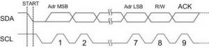
Slave address bits are used to address a specific slave device on the bus. 7 bit address let the master to address maximum of 128 slaves on the bus. Although address 0000 000 is reserved for general call and all address of the format 1111 xxx are reserved in many devices. That means 119 devices can share an I2C bus. In I2C bus the MSB of the address is transmitted first.
The 8th bit in the byte is READ/WRITE control bit. If this bit is set, the master will read the next byte from the slave, otherwise, the master will write the next byte on the bus to the slave. When a slave detects its address on the bus, it knows that it is being addressed and it should acknowledge in the ninth clock cycle by pulling SDA to low. If the addressed slave is not ready or for any reason does not want to respond to the master, it should leave the SDA line high in the 9th clock cycle. It is considered as NACK. In case of NACK, the master can transmit a STOP condition to terminate the transmission, or a REPEATED START condition to initiate a new transmission.
Data Byte Format
Like other bytes, data bytes are 9 bits long too. The first 8 bits are a byte of data to be transmitted and the 9th bit, is ACK. If the receiver has received the last byte of data and does not wish to receive more data, it may signal a NACK by leaving the SDA line high. The master should terminate the transmission with a STOP after a NACK appears. In data bytes, like address bytes, MSB is transmitted first.
Combining Address and Data Bytes
In I2C, normally, a transmission is started by a START condition, followed by an address byte (SLA+R/W), one or more data bytes and finished by a STOP condition.
Clock stretching
One of the features of the I²C protocol is clock stretching. It is a kind of flow control. If an addressed slave device is not ready to process more data it will stretch the clock by holding the clock line (SCL) low after receiving (or sending) a bit of data so that the master will not be able to raise the clock line (because devices are wire-ANDed) and will wait until the slave releases the SCL line to show it is ready for the next bit.
Arbitration
I2C protocol supports multi-master bus system. It doesn’t mean that more than one master can use the bus at the same time. Each master waits for the current transmission to finish and then start to use the bus. But it is possible that two or more masters initiate a transmission at about the same time. In this case the arbitration happens.
Each master has to check the level of the bus and compare it with the levels it is driving; if it doesn’t match, that master has lost the arbitration, and will switches to slave mode. In the case of arbitration, the winning master will continue its job. Notice that neither the bus is corrupted nor the data is lost.
Multi-byte burst write
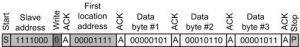
Burst mode writing is an effective means of loading data into consecutive memory locations. It is supported in I2C like SPI and many other serial protocols. In burst mode, we provide the address of the first memory location, followed by the data for that location. From then on, consecutive bytes are written to consecutive memory locations. In this mode, the I2C device internally increments the address location as long as STOP condition is not detected. The following steps are used to send (write) multiple bytes of data in burst mode for I2C devices.
- The master generates a START condition.
- The master transmits the slave address followed by a zero bit (for write).
- The master transmits the address of the first location.
- The master transmits the data for the first location and from then on, the master simply provides consecutive bytes of data to be placed in consecutive memory locations in the slave.
- The master generates a STOP condition.
The following figure shows how to write 0x05, 0x16 and 0x0B to 3 consecutive locations starting from location 00001111 of slave 1111000.
Multi-byte burst read
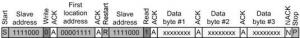
Burst mode reading is an effective means of bringing out the contents of consecutive memory locations. In burst mode, we provide the address of the first memory location only. From then on, contents are brought out from consecutive memory locations. In this mode, the I2C device internally increments the address location as long as STOP condition is not detected. The following steps are used to get (read) multiple bytes of data using burst mode for I2C devices.
- The master generates a START condition.
- The master transmits the slave address followed by a zero bit (for writing the address).
- The master transmits the address of the first memory location.
- The master generates a RESTART condition to switch the bus direction from write to read.
- The master transmits the slave address followed by a one bit (for read).
- The master clocks the bus 8 times and the slave device provides the data for the first location.
- The master provides an ACK.
- The master reads the consecutive locations and provides an ACK for each byte.
- The master gives a NACK for the last byte received to signal the slave that the read is complete.
- The master generates a STOP condition.
The following figure shows how to read three consecutive locations starting from location 00001111 of slave number 1111000.
The following table lists some addresses that have special meaning. A write to address 0 is a general call address, and is used by the master to send commands to all slaves. The 10-bit address mode gives two address bits in the first frame and 8 more address bits in the second frame. The direction bit for 10-bit addressing is in the first frame.
| Address | R/W | Description |
|---|---|---|
| 0000 000 | 0 | General call address |
| 0000 000 | 1 | Start byte |
| 0000 001 | x | CBUS address |
| 0000 010 | x | Reserved for different bus formats |
| 0000 011 | 0 | Reserved |
| 0000 1xx | x | High speed mode |
| 0000 0xx | x | 10-bit address |
| 0000 1xx | X | Reserved |
Recent Comments