
Interfacing the Keyboard to the CPU
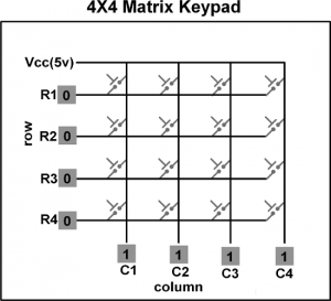
To reduce the microcontroller I/O pin usage, keyboards are organized in a matrix of rows and columns. The CPU accesses both rows and columns through ports; therefore, with two 8-bit ports, an 8×8 matrix of 64 keys can be connected to a microprocessor.
- Keys on a keyboard are organized in a matrix of rows and columns
- The microcontroller accesses both rows and columns through GPIO ports.
- When a key is pressed, a row and a column make contact in order to detect the particular key.
Before proceeding further it is assumed that you are familiar with the following:
4×4 Keypad on EduARM4 Trainer Board
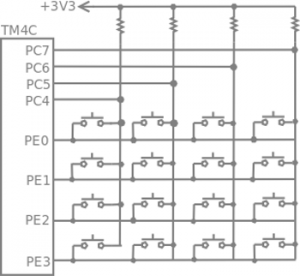
The above figure shows a 4×4 keypad matrix connected to two ports on the EduARM4 board. The rows are connected to an output port (PE0 – PE4) and the columns are connected to an input port (PC4 – PC7). All the input pins should have pull-up resistor connected (select an internal pull-up resistor). If no key has been pressed, reading the input port will yield 1s for all columns. If all the rows are driven low and a key is pressed, the column of that key will read back a 0 since the key pressed shorted that column to the row that is driven low. It is the function of the microprocessor to scan the keyboard continuously to detect and identify the key pressed.
Key press detection
Remember, as mentioned above, the keys are not simply connected to the micro controller as input pins, rather they are arranged in columns and rows in order to save the number of GPIO pins required to read from a keyboard.
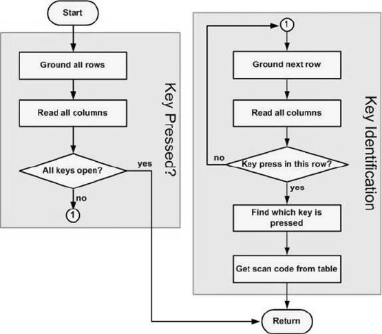
To detect the key pressed, the microprocessor drives all rows low, then it reads the columns. If the data read from the columns is D7(PC7) – D4(PC4) = 1111, no key has been pressed and the process continues until a key press is detected. However, if one of the column bits has a zero, this means that a key was pressed. For example, if D7 – D4 = 1101, this means that a key in the D5 column has been pressed.
Key identification
After a key press is detected, the microprocessor will go through the process of identifying the key. Starting from the top row, the microprocessor drives one row low at a time; then it reads the columns. If the data read is all 1s, no key in that row is activated and the process is moved to the next row. It drives the next row low, reads the columns, and checks for any zero. This process continues until a row is identified with a zero in one of the columns. The next task is to find out which column the pressed key belongs to. This should be easy since each column is connected to a separate input pin.
Jumper Selection:
All the Jumpers (J7 – J10) Should be Open on the EduARM4 Trainer Board for 4×4 keypad project.
- Port E pins 3-0 are used for rows and configure as output digital pins. configure these pins as open drain output also, which means they are driven low actively but not driven high.
- Open drain output prevents port damage when two keys of the same column are pressed at the same time.
- If output pins are driven high and low and two keys of the same column are pressed, it will short the output low to output high of the adjacent pin and cause damages to the output pins.
- configure Port C pins 7-4 as input digital pin with the internal pull-up resistors enabled. This will ensure that the input pins read 1 when no key is pressed.
Flowchart for Key Press Detection and Identification
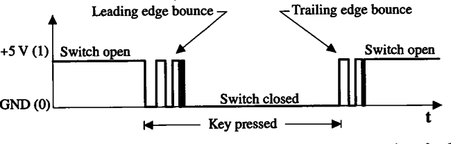
Debounce
See Also
Task 1
- Assign a key code to each switch (SW0 – SW15). Whenever a particular key is pressed its corresponding key code should be displayed on the CCS CIO console. (You should take care of debounce and multiple key pressed at the same time).
Recent Comments