
| OVERVIEW | SYSTICK INTERRUPT | TASKS |
Using Systick Timer with TM4C123GH6PM Launchpad
So far we have learned that how to program general purpose input output(GPIO) of ARM Cortex M-4. But we have not generated the delay in micro controller. In this section we will generate delay using different methods and blink on board LEDs. There are two types of delays that can be generated by our program:
- Software delay
- Hardware delay
Software delay
- This type of delay is nothing but making the controller busy, doing the task which will occupy a certain duration. For example if we want our friend to wait for us then instead of telling him to wait we can simply engage him in other task. But the generated time may or may not be so accurate.
Example: In C code if we can use this for loop for generating a delay of 1 second.
-
void delay_1sec(void)
-
{ -
for( unsigned long i = 0; i <= 3000000; i++ )
-
; -
}
This method doesn’t generate the accurate time delay, but approximate. For generation of accurate delay in microsecond we prefer hardware delay.
Hardware delay
- The hardware delay is most precise method to generate delay. In this method we use timer which is the most popular and useful feature of microcontrollers. Generally delay with timer is like waiting a bucket to be empty if we make a small hole to leak its filled liquid more the liquid more time it will take to empty the bucket. In this article, we are going to use a special timer called systick timer. In our micro controller we have six 64 bit and six 32 bit timer excluding systick timer. This timer is very useful and plays very important role in RTOS design. We will see other timers later. In our micro controller, Systick timer is 24 bit wide. For the generation of delay, at first we need to make sure that our controller is working on the clock frequency as we are expecting. This step is required to select the clock source only at external crystal without PLL.
SysTick Timer
SysTick is a simple counter that we can use to create time delays and generate periodic interrupts. It exists on all Cortex-M microcontrollers, so using SysTick means the system will be easy to port to other microcontrollers.
As we learned earlier that modifying registers are the key for configuration and desired functionality. Hence systick timer can be used by modifying these registers.
- Systick Reload value (STRELOAD)
- Systick Control and Status Register (STCTRL)
- Systick Current Value (STCURRENT)
Systick Reload Value Register
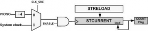
- This register acts like a bucket filled with a liquid that will be empty after some time duration and we will get acknowledgement by a change in flag bit in STCTRL Register. This register is 24 bit wide.
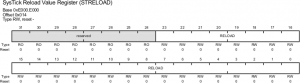
Since this register is 24 bit wide it can store upto 0xFFFFFF or 16777215. when we load any value into this register and trigger the timer it starts to count down and when the value reaches to 0 it sets the COUNT FLAG. We will see how to reload and check flag bit in the next few steps.
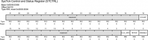
Systick control and Status register
- This register is shown in the following figure
| Bit | Name | Description |
|---|---|---|
| 0 | Enable | Enable 0: the counter is disabled 1: enables SysTick to begin counting Down |
| 1 | INTEN | Interrupt Enable 0: Interrupt generation is disabled 1: when SysTick counts to 0 an interrupt is generated |
| 2 | CLK_SRC | Clock Source 0: Precision internal oscillator (PIOSC) divided by 4 1: System clock |
| 16 | COUNT | Count Flag 0: the SysTick has not counted Down to zero since the last time this bit was read 1: the SysTick has counted Down to Zero Note: this flag is cleared by reading the STRCTL or writing to STCURRENT Register |
We need to set our main clock to system clock by setting CLK_SRC to 1. And we don’t want interrupt method so INTEN bit will be 0. Now we are going to trigger our timer by writing ENABLE bit 1 so writing 0x5 will trigger our timer at the same time it will also set the configuration. Now the loaded value will be started to count down. When the timer gets rollover the bit 16 will set to one. hence we need to monitor 16th bit.
If INTEN=1, when the COUNT flag is set, it causes an interrupt via the NVIC. INTEN is D1 of the STCTRL register.
Systick Register Summary
| Address | 31-24 | 23-17 | 16 | 15-13 | 2 | 1 | 0 | Name |
|---|---|---|---|---|---|---|---|---|
| $E000E010 | o | 0 | COUNT | 0 | CLK_SRC | INTEN | ENABLE | NVIC_ST_CTRL_R |
| $E000E014 | o | 24-bit RELOAD value | NVIC_ST_RELOAD_R | |||||
| $E000E018 | o | 24-bit CURRENT value of SysTick counter | NVIC_ST_CURRENT_R | |||||
Delay time calculation
Since we are working with external clock i.e. 16 MHz, each pulse generated by the clock source will have:
1/XTAL frequency = 1/(16*10^6) = 62.5ns time period.
So if we load 253 into the RELOAD register and trigger the counter it will count down with next pulse and will take 62.5ns to change its value from 253 to 252. Hence, In order to generate the delay, we can calculate the approximate value that has to be loaded into this register by the formula-
Reload Value = XTAL*Time delay
one extra clock delay is already included to set the flag for rollover, hence we get one extra clock delay. By subtracting by one will give exact time delay.
Reload Value = (XTAL*Time Delay)-1
Remember that in one shoot, it can only take 0xFFFFFF maximum value. Therefore in one shoot, we can only generate maximum of Time delay
TimeDelay = (ReloadValue+1)/XTAL=16777215+(1/(16*10^6))
TimeDelay = 1.048575937 sec.
Example: For generating 1 sec of delay the value that has to be loaded into the RELOAD Register
Reload Value = (XTAL*Time delay)-1
Reload Value = (16*10^6*1)-1
Reload Value = 15999999
SysTick timer Initialization
There are four steps to initialize the SysTick timer.
- Clear the ENABLE (NVIC_ST_CTRL_R) bit to turn off SysTick during initialization.
- Set the RELOAD (NVIC_ST_RELOAD_R) register.
- Write to the NVIC_ST_CURRENT_R value to clear the counter.
- Write the desired mode to the control register, NVIC_ST_CTRL_R.
- Set the CLK_SRC bit specifying the core clock will be used.
- We must set CLK_SRC=1 bit specifying the core clock will be used, because CLK_SRC=0 external clock mode is not implemented on the LM3S/TM4C family.
- Set INTEN (NVIC_ST_CTRL_R) to enable interrupts, but in this first example we clear INTEN so interrupts will not be requested.
- Set the ENABLE (NVIC_ST_CTRL_R) bit so the counter will run.
When the CURRENT (NVIC_ST_CURRENT_R) value counts down from 1 to 0, the COUNT flag is set. On the next clock, the CURRENT is loaded with the RELOAD value. In this way, the SysTick counter (CURRENT) is continuously decrementing. If the RELOAD value is n, then the SysTick counter operates at modulo n+1 (…n, n-1, n-2 … 1, 0, n, n-1, …). In other words, it rolls over every n+1 counts.
The COUNT flag could be configured to trigger an interrupt. However, in this first example interrupts will not be generated.
Source Code
Delay in 62.5ns units
-
/* delay is in 62.5ns units */ -
void SysTick_Wait(uint32_t delay)
-
{ -
NVIC_ST_CTRL_R = 0; /* (1) disable SysTick during setup */
-
NVIC_ST_RELOAD_R = delay-1; /* (2) number of counts to wait */
-
NVIC_ST_CURRENT_R = 0; /* (3) any value written to CURRENT clears */
-
NVIC_ST_CTRL_R |= 0x5; /* (4) enable SysTick with core clock */
-
while((NVIC_ST_CTRL_R&0x00010000)==0) {
-
; /* wait for COUNT flag */
-
} -
}
One Second Delay
-
void One_Second_Delay(void)
-
{ -
NVIC_ST_CTRL_R = 0; /* disable SysTick during setup */
-
NVIC_ST_RELOAD_R = 15999999; /* Reload Value goes here */
-
NVIC_ST_CTRL_R |= 0x5; /* enable SysTick with core clock */
-
while( (NVIC_ST_CTRL_R & (1<<16) ) == 0)
-
; /* Monitoring bit 16 to be set */
-
NVIC_ST_CTRL_R = 0; /* Disabling SysTick Timer */
-
}
Recent Comments