
MOTIVATION
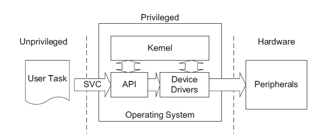
1.To separate user space from kernel space and to avoid direct access to hardware (peripherals)
on ARM Cortex M4.
2.User need not to know about actual hardware to access it.
INTRODUCTION
A typical embedded system by default can have limited features. By exposing internal
hardware can give more features to user as he wants.
With same hardware, we can separate user space from kernel space. So, flow of the code can
be changed using SVC calls in order to avoid direct access to peripherals.
SYSCALLS
A system call is a method in which a software requests a service from the kernel or OS on
which it is running. If it is intended to separate the system into privilege levels, it is inevitable
that the application level needs call the kernel to have access to, for example, hardware services
or whatever else is critical to the security and stability of the system. A common way to
implement system calls in is to use the software interrupt Supervisor Call (SVC). The SVC acts
as an entry point for a service that requires privileges to run.
SVC
The SVC (Supervisor Call) is exception type 11, and has a programmable priority level. In
many systems, the SVC mechanism can be used by syscalls to allow application tasks to access
system resources. In systems with high-reliability requirements, the application tasks can be
running in unprivileged access level, and some of the hardware resources can be set up to be
privileged accessed only (using MPU). The only way an application task can access these
protected hardware resources is via services from the OS. In this way, an embedded system
can be more robust and secure, because the application tasks cannot gain unauthorized access
to critical hardware.
In some cases, this also makes the programming of the application tasks easier because the
application tasks do not need to know the programming details of the underlying hardware if
the OS services provide what the task needs. SVC also allows application tasks to be developed
independently of the OS because the application tasks do not need to know the exact address
of the OS service functions. The application tasks only need to know the SVC service number
and the parameters that the OS services requires.
The SVC exception is generated using the SVC instruction. An immediate value is required for
this instruction, which works as a parameter-passing method. The SVC exception handler can
then extract the parameter and determine what action it needs to perform.
When the SVC handler is executed, the immediate data value can be determined in the SVC
instruction by reading the stacked Program Counter (PC) value, then reading the instruction
from that address and masking out the unneeded bits. However, the program that executed the
SVC could have either been using the main stack or the process stack. So, to determine which
stack was used for the stacking process before extracting the stacked PC value, the link register
value when the handler is entered is used.
PENDSV
PendSV (Pended Service Call) is exception type 14 and has a programmable priority level. The
PendSV Exception is triggered by setting its pending status by writing to the Interrupt Control
and State Register. Its pending status can be set inside a higher priority exception handler and
executed when the higher-priority handler finishes. Using this characteristic, we can schedule
the PendSV exception handler to be executed after all other interrupt processing tasks are done,
by making sure that the PendSV has the lowest exception priority level.
UNPRIVILEGED THREAD AND PRIVILEGED THREAD
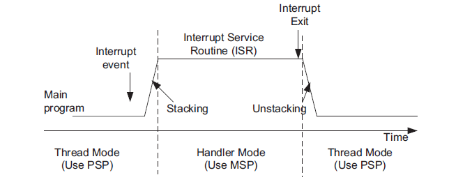
Embedded systems often use separate memory areas for application stack (unprivileged thread)
and the kernel stack with 2 stack pointers: PSP and MSP. As a result, the PSP is used for
unprivileged thread and switching of SP selection takes place in exception entry and exception
exit to MSP. The automatic “Stacking” and “Unstacking” stages use PSP. The separating stack
arrangement can prevent a stack corruption or error in an application task from damaging the
stack use by the OS. It also simplifies the OS design and hence allows faster context switching.
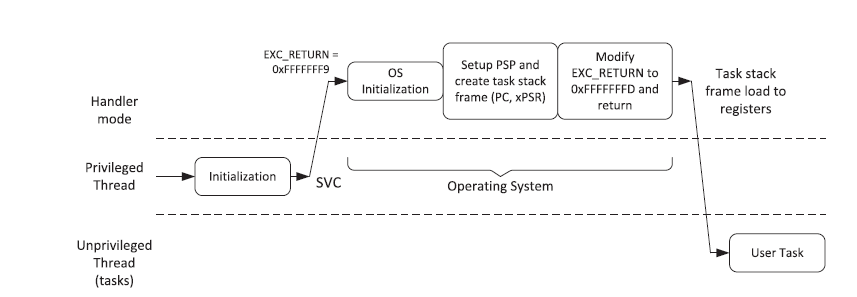
Initially after power on, the system is in privileged mode. Once separate stack for application
and kernel are setup, peripherals are initialized and the MPU is set up, we switch to user mode
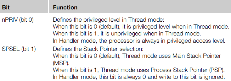
using CONTROL register. it is only possible to write or read the CONTROL register in handler
mode (within an exception handler) or in privileged threads. The CONTROL register has only
2 configurable bits.
MEMORY PROTECTION UNIT
An optional part of the ARMv7-M architecture is the support of a Memory Protection Unit
(MPU). This is a fairly simplistic device (compared to a fully blow Memory Management Unit
(MMU) as found on the Cortex-A family), but if available can be programmed to help capture
illegal or dangerous memory accesses.
As this project main theme is to protect the hardware from the user thread to protect it we
should use this memory protection unit(MPU).
MPU divides the memory map into a number of regions with privilege permissions and access
rules.
Features of the MPU are as follows:
• Prevents an untrusted application from accessing protected memory regions for the purpose
of intellectual property infringement.
• Prevents user applications from corrupting data used by the operating system.
• Separates data between processing tasks by blocking tasks from accessing other data.
• Allows memory regions to be defined as read-only so that vital data can be protected.
• Detects unexpected memory access
so it provides Memory protection,Peripheral protection,Privileged code access protection.
A memory region will have the following Memory type,Memory attributes,region number.
Memory types are
1. Normal: refers to data or code memory space such as, Flash or SRAM
2. Device: refers to memory mapped peripherals .
3. Strongly-ordered: refers to memory whose access always follows the program order
(i.e.,TCM)
Memory attributes are
1. Shareable or non-shareable (S)
2. Cacheable or non-cacheable (C)
3. Memory access permission (AP)
4. Access for Instruction Fetch (XN)
5. TEX and B are other bit-fields, which in combination with the above bit-fields, define
the memory attribute for each MPU memory region
The MPU registers need to be programmed and enabled before use. This is usually done in the
initialization phase of any application running on the target MCU, after the system startup
Configuring MPU:
1. Select the memory region.
2. Configure the attributes for the selected memory region (TEX, S, C, B, AP, XN). – Repeat
above two steps for all valid memory regions
3. Enable MPU.
Flow chart :
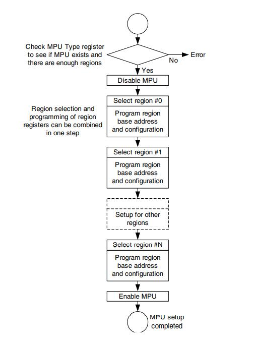
If access is gained to an area of memory without the required permissions, a memory
management fault is raised.
Note:
The MPU region attribute can be updated at run-time to satisfy different requirements. To
update the attribute of a region, consider the following actions:
1. The region must be disabled before changing the attributes.
2. To avoid unexpected behavior, the interrupt routine must be disabled before the update.
3. The access to the MPU registers should be aligned.
MPU configuration registers are located at system level in memory map so we can modify
MPU registers only in privileged mode.
MPU configuration registers are given below.
1.MPU_TYPE_R :this register defines the following
•
How many MPU supported regions are there.
Ex : NVIC_MPU_TYPE_R = 0X800.
The above register says for three regions MPU is enabled.
2.MPU_CTRL_R :this register defines the following
•whether MPU is enabled or not (bit 0)
•what will happen when a MPU disabled region is being accessed in priviledged or
unpriviledged mode.(bit 0 and bit 2)
•Whether MPU is enabled in FAULT ISR,NM ISR. (bit 1).
•Remaining bits were reserved.
Ex : NVIC_MPU_CTRL_R =0X07;
In the above register
•As Bit 0 is ‘1’ it says MPU is enabled
•As Bit 1 is ‘1’ it says MPU is enabled in FAULT ISR,NMI ISR.
•As Bit 2 and Bit 1 are ‘1’ it says any access by privileged software that does not
address an enabled memory region behaves as defined by the default memory map Any
access by unprivileged software that does not address an enabled memory region causes
a memory management fault.
2. To avoid unexpected behavior, the interrupt routine must be disabled before the update.
3. The access to the MPU registers should be aligned.
MPU configuration registers are located at system level in memory map so we can modify
MPU registers only in privileged mode.
MPU configuration registers are given below.
1.MPU_TYPE_R :this register defines the following
How many MPU supported regions are there.
Ex : NVIC_MPU_TYPE_R = 0X800.
The above register says for three regions MPU is enabled.
2.MPU_CTRL_R :this register defines the following
•whether MPU is enabled or not (bit 0)
•what will happen when a MPU disabled region is being accessed in priviledged or
unpriviledged mode.(bit 0 and bit 2)
•Whether MPU is enabled in FAULT ISR,NM ISR. (bit 1).
•Remaining bits were reserved.
Ex : NVIC_MPU_CTRL_R =0X07;
In the above register
•As Bit 0 is ‘1’ it says MPU is enabled
•As Bit 1 is ‘1’ it says MPU is enabled in FAULT ISR,NMI ISR.
•As Bit 2 and Bit 1 are ‘1’ it says any access by privileged software that does not
address an enabled memory region behaves as defined by the default memory map Any
access by unprivileged software that does not address an enabled memory region causes
a memory management fault
3.MPU_BASE_R :this register defines the following
•Base address of the region
•Region number is changed when valid bit is’1’. Valid bit is bit 4 in the register. And
region number is from bit 3 to bit 0
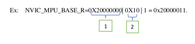
In the above example “box 1 “ determines the base address. In ”box 2” ‘1’ determines valid
bit is 1.and last three bits determine the region number
4.MPU_ATTR_R : this register defines the following
•required attributes configutration in the region specified.
•size of the region.
•Enabling the MPU to the region.(bit 0)
Bit 28 -XN attribute
Bit 26:24 – AP attribute
Bit 21:19 – TEX attribute
Bit 18 -shareable attribute
Bit 17 – cacheable attribute.
Bit 16 – Bufferable attribute.
Bit 15:8 -sub region disable bits
Bit 5:1 – size of the region
Bit 1 – Region enable bit.
Ex :NVIC_MPU_ATTR_R = 0X02000039
As bit 26:24 is “010” which specifies in this region there is read write access to priviledge
thread and only read access to user thread.
As bit 5:1 is “11100”=28 so actual size is 2^(28+1) bytes = 0.5GB.
As bit 1 is’1’ to this region MPU enabled .so this region is called enabled region.
Note : while specifying base address in MPU_BASE register least significant 5 bits were
ignored.
Note : while specifying base address in MPU_BASE register least significant 5 bits were
ignored.
All this explanation is written by understanding the content in the tm4c123gh6pm datasheet in
chapter 3 :section 3.1.4,3.6. and in the third reference given below.
CODE FLOW
Step 1:
Disabling interrupts reason why we disable interrupts is still the required stack is not initialized
, after initializing the stack and doing all required configurations we can enable interrupts so
that there will be no issue.
Command for disabling interrupts is __asm(“CPSID I”)
Step 2:
Initializing MPU as below
NVIC_MPU_TYPE_R = 0x800;
NVIC_MPU_BASE_R = 0x00000000 | 0x10 | 0;
NVIC_MPU_ATTR_R = 0x03000039;
NVIC_MPU_BASE_R = 0x20000000 | 0x10 | 1;
NVIC_MPU_ATTR_R = 0x03000039;
NVIC_MPU_BASE_R = 0x40000000 | 0x10 | 2;
NVIC_MPU_ATTR_R = 0x02000039;
NVIC_MPU_CTRL_R= 0X07;
From above one we can observe MPU is enabled in 3 regions.and description of the registers
,its need is given in MPU theory part above.
Step 3:
Giving priority to Pend SV ,SVC handler.
Note: for pend sv we should give least priority.(priority is less when priority number is high)
NVIC_SYS_PRI2_R = (NVIC_SYS_PRI2_R & 0x1FFFFFFF) | 0x10000000; // priority 4
NVIC_SYS_PRI3_R= (NVIC_SYS_PRI3_R & 0xFF1FFFFF) | 0x00E00000; // priority 7
NVIC_SYS_PRI2_R is used to give priority to SVC,NVIC_SYS_PRI3_R is used to give
priority to pend sv.
Step 4:
Initializing UART, other required peripherals
Note: In this project inputs are taken through UART
Step 5:
Initializing stacks one is for priviledged mode and other is for user mode.
psp = &u_stacks[STACKSIZE -16];
msp = &k_stacks[STACKSIZE -1];
Step 6:
switching to user mode by configuring the control register.
__asm
(”
LDR R0, =msp \n”);
__asm
__asm
__asm(”
(”
(“LDR R2, [R0] \n”);
MSR MSP, R2″);
LDR R1, =psp \n”);
__asm
__asm
__asm
__asm
__asm
__asm
__asm
__asm
__asm
__asm
__asm
__asm(”
(”
(”
(”
(”
(”
(”
(”
(”
(”
(”
(“LDR R2, [R1]
\n”);
MSR PSP, R2″);
CPSIE I
\n”);
MOV R1, #0x3″);
MSR CONTROL, R1 \n”);
POP {R4-R11}
\n”); //restore r4-11
POP {R0-R3} \n”);
POP {R12} \n”);
POP {LR}
\n”); //discard LR from stack ()
POP {LR}
\n”); //start location user_main
POP {R1}
\n”); //discard PSR
BX LR
\n”); //start first thread
First 3 lines is used to point the stack defined for priviledged mode to MSP.next 3 lines is used
the point the stack defined for user mode to PSP.
In line 7 we enabled the interrupts and after that configuring control register to move from
priviledged to user mode ,
When “BX LR” statement executes PC will point to the user main.
Step 7:
Now the code is in user thread so a while (1) loop is used for the sake of not to return to
priviledged mode .
Step 8:
User will give inputs through UART and command is get processed if command matches with
any of the valid command then a svc call for respective command is called.
Svc call is called by the following instruction
__asm(“svc #0x1”). In this “1” represents the SVC number.
Step 9:
How arguments were passed to handler:
generally in cortex m3 while calling a function with the parameters then that parameters will
be actually stored in R0,R1,R2,R3 so in our code also before calling svc we used a function to
pass the required parameters and that will be stored in R0,R1,R2,R3 so when I entered to pend
sv handler to do the task i can take the arguments from R0,R1,R2,R3 and I can use it to do the
required task.
In svc handler we set the pend sv bit .
Step 10: PEND SV handler.
__asm(” MRS R0, PSP “);
__asm(“B SVC_Handler_main \n”);
We can get svc number by writing following line
svc_number = ((char *)svc_args[6])[-2] (in this line svc_args contains the PSP
value)
now the actual task will be done and returns to the user mode.
Info:
What happens when user tries to change memory content of peripherals?
Ans :When user tries to change content of memory in peripheral region execution flow will go
to fault isr handler.in fault isr handler written the code such that it will return back to user
thread again.use of this thing is rebooting is not required when entered to fault ISR.
__asm(“MRS R0,PSP”);
__asm(“ADD R1, R0,#24 “);
__asm(“LDR R0,[R0,#24]”);
__asm(“ADD R0,R0,#4 “);
__asm(“STR R0,[R1]”);
OUTPUT
Case 1: giving set and get commands after configuring of respective port is done.
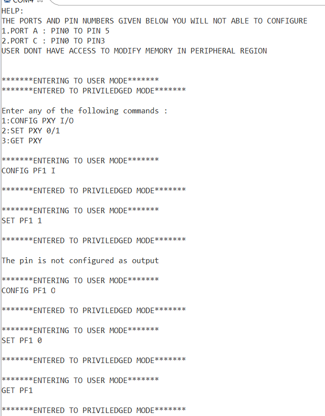
Case 2: giving “set” or “get” command with out configuring the respective port
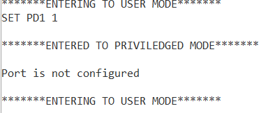
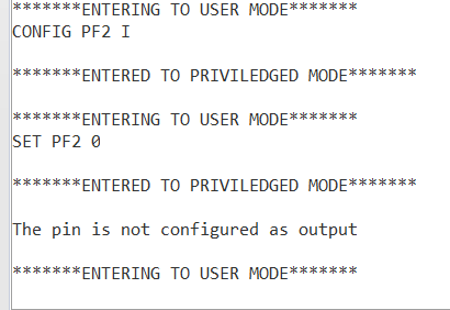
Case 3 :setting a pin in the port which is not configured as output
Case 4:Trying to configure a port which is having no access to configure.
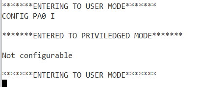
In above outputs we have a message like “entered to privileged mode “ which specifies that
task is being done in privileged mode and while returning back to user mode it will display the
message “entering to user mode”.
CHALLENGES
1. Configuration of MPU
2. Understanding of getting svc_number when we entered to SVC handler.Future Scope:
1.in this project we have given access to configure GPIOs for digital applications
this can be extended to configure GPIO registers related to analog applications,
configuring GPIOs for alternate functions also.
2.can give chance to user to configure GPIOs for interrupt or polling mode.
3.we have written code for only for one user thread this can be extended to multi
user threads, multi privileged threads and switching between them using
SYSTICK,PEND SV,SVC .
REFERENCES
[1] The Definitive Guide to ARM Cortex-M3 and Cortex-M4 Processors, Joseph Yiu
[2] https://antoniogiacomelli.com/2020/10/25/separating-user-space-from-kernel-space-on-
arm-cortex-m3/
[3] https://blog.feabhas.com/2013/02/setting-up-the-cortex-m34-armv7-m-memory-protection-
unit-mpu/
[4] TM4C123GH6PM datasheet.
Recent Comments