
INTRODUCTION
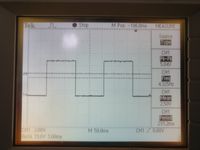
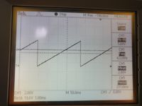
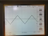
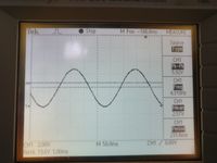
The aim of this project is to generate different signals using TIVA microcontroller. The project uses TIVA C Series TM4C123GH6PM board which has ARM Cortex-M4 microcontroller. The micro controller is interfaced with LTC1661 DAC(Digital to Analog Converter) to generate analog signals which are displayed on oscilloscope. The different signals generated are sine, triangular, sawtooth and square waves. The signal frequency can also be varied and displayed.
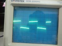
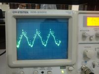
The waveforms are as displayed below:
METHODOLOGY
> Basic Idea– A signal can be represented as a sequence of impulses. We can use this idea to send a particular sequence of values to a DAC, which produces the required signal. We can use LUTs to store the values for each type of signal.
> Generation of Lookup table– A look up table of 120 samples, each of 12 bit, for one period of the waveform is generated using MATLAB for sine, square, triangular and sawtooth waves.
> Transmission of sample values– Sample values of the look up table are transmitted serially and synchronously through SPI protocol from Microcontroller to DAC. Two devices communicating with synchronous serial interfaces (SSI) operate from the same clock (synchronized). With a SSI protocol, the clock signal is included in the interface cable between devices. Typically, the master device creates the clock, and the slave device(s) uses the clock to latch the data in and send data out.
> Working of SPI– The SSI uses only 2 pins for data transfer-Sclk for clock and Dout for data transfer. A 3rd pin of the microcontroller acts as SS (Slave select), which is used to initiate and terminate the data transfer. For the LTC 1661, SS is connected to pin 1, Sclk to pin 2 and Dout to pin 3.
SWITCHING OF WAVEFORMS
This is done by enabling interrupt on switch SW1 of Tiva board and indicated by glowing LED. When red led glows it displays sine wave on the oscilloscope, similarly blue led for triangular wave, green led for sawtooth wave, and mix of green and blue led for square wave.
INCREMENTING FREQUENCY
Each time the switch SW2 is pressed, frequency of the waveform is incremented by 6Hz. Default frequency is 10Hz and maximum of 1KHz frequency can be achieved.
CHALLENGES FACED
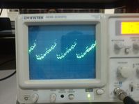
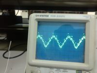
Initially we were using 12 bit parallel DAC- AD7541A. Because of 12 bits, we havd 4096 states and we were using 120 samples to generate one period of waveform. So when a state transition occurs, due to different bit delays states were transitioning to some arbitrary states which were causing noise(glitches) in the form of spurs in the output waveform. We allayed this problem by using LTC1661 serial DAC.
The waveforms obtained with parallel DAC are as follows:
Video link
Recent Comments