
Background
Mobile telemedicine systems have been under technological improvements since recent past. Until a few years ago, the job of an ambulance was to simply transport the causality to the hospitals. Modern ambulances not only transport the patient but start stabilizing the patient clinically at the earliest on board. This improvement has proved to be life saving for such services in remote areas.
Self-balancing platform proposed by us can add to the quality of service to the patient on-board the ambulance. The platform can be transformed into the stretcher inside the ambulance to compensate for the ambulance motions and hence make the patient feel more comfortable.
In addition to above scenario, the proposed platform can also be effectively used to avoid the sea-sickness in ships. Moving ships experience pitch, roll and yaw rotations on the sea surface which leads to sea-sickness to people on-board. The platform will be able to compensate for pitch and yaw rotations of the ship and hence reduce the chances of sea-sickness up to a great extent to the user.
Objective
To design and develop an electro-mechanical platform which can automatically balance the objects placed over it in the presence of surrounding mechanical disturbances.
Theory
The platform inclination is sensed by accelerometer and gyroscope sensors and streamed to the microcontroller. Microcontroller filters the input stream using complementary filter and implement a control loop for driving servo motors connected to the same platform through PWM. Thus a closed-loop is established which compensates for the disturbances from the environment.
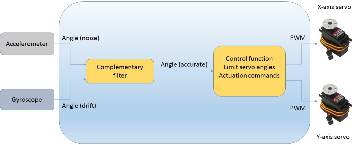
Fig 1. Block Diagram
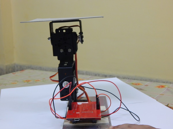
Fig 2. Platform
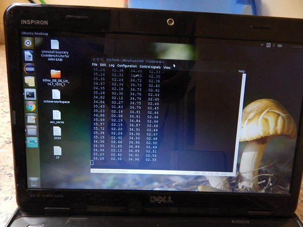
Fig 3. A snapshot of the readings from the platform
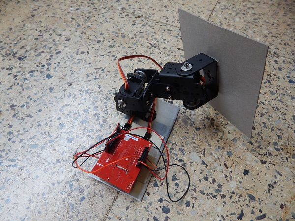
Fig 4. Platform showing the effect of drift due to gyro reading only
Components used
Electronic parts:
Sensor Hub Booster Pack: Accelerometer and Gyroscope
TM4C123G LaunchPad Evaluation Board
Standard Dual Ball Bearing Servo: 2 No’s (Robokits India)
connecting wires: 6 No’s
Mechanical parts:
L Shaped Interconnect Servo Bracket: 2 No’s (Robokits India)
Short U Shape Aluminium Servo Bracket: 2 No’s (Robokits India)
Multipurpose Aluminium Standard Servo Bracket: 2 No’s (Robokits India)
Metal Horn for Servo 25T: 2 No’s (Robokits India)
Servo bracket washers: 2 No’s (DESE workshop)
Base platform: (DESE workshop)
M3 screws and nuts: 10 No’s
Double sided tape
Software:
Eclipse IDE for C/C++ Developers
TivaWare Peripheral Driver Library: I2C, PWM, UART and GPIO
Complementary/Kalman filter implementation
Control function implementation
TivaWareTM Sensor Library: DCM and sensor fusion algorithms (optional)
Working principle
Accelerometer and Gyroscope are integrated on MPU9150 IC which is available on sensor hub booster pack. MPU9150 has I2C interface which can be used by TM4C123G microcontroller to read sensor data.
Accelerometer alone can be used for inclination angle measurement using the below formulae
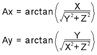
but it suffers from a lot of angle noise due to every other force working on our platform besides gravitational force. Hence accelerometer readings can be relied only in long term duration.
Similarly, gyroscope suffers from drift in angle readings as angle calculation is done by integrating angular velocity and integration process accuracy is limited by sampling period of digital system.
Hence, what we have to do is to collect required data from both accelerometer and gyroscope, process it through filtering before further processing to provide output to the motors. Complementary filter or kalman filter best suits for such requirement. For this project we used complementary filter as it gave quite satisfactory results.
For complementary filter, we can assign some weigtage to each of these sensors, say x to gyro data and y to accelerometer data; but both should add up to 1; i.e y = 1-x. We varied x from 0.95-0.98 and y from 0.05-0.02 and the filtered angles were quite accurate with overall stability of the platform. The equation we used for complementary filter is given below:
ANGLE = x*(ANGLE + gyroscope_rate*dt) + y*accelerometer_angle
The angle equation given above is to calculate angle for both x-axis and y-axis.
These angles are then used to calculate pwm pulse width which goes to the servo motors. If the angle is greater than 0, the equation for pwm calculation is:
pwmcount = 22.22*ANGLE + 3000
and if the angle is smaller than 0, the equation is:
pwmcount = 20.55*ANGLE + 3000
The multiplying factors are different as the motor operation is not perfectly linear in entire 180 degree range. 3000 corresponds to PWM count for vertical positioning (0 degree) of the servo motor. Similarly, 5000 and 1150 correspond to PWM counts for +90 degree and -90 degree positioning of the servo motors. pwmcount is issued as actuator command to servo motors.
Result and Performance
The platform developed is able maintain accurate pitch and roll angles required for proper balancing of the platform. The platform balances the objects placed over it and hence prevent them falling from it in presence of mechanical disturbances. The performance of platform can further be evaluated by following the link given in the “Video link” section below.
Links to software
Embedded software of the project is available on moodle.
Video link
Please follow the following link for demonstration video of the platform ……………
Recent Comments