
   1 What we have to do???
   2 What is this about???
   3 Is there any Physics over there???
   4 How does control system work???
   5 What we tried to do!!!!
   6 How Software works???
   7 Finally this one stands!!!!!!!!!
(B) LINE FOLLOWER USING FREESCALE LINE SCAN CAMERA
   1 Understanding the line scan camera.
   2 Timing requirements.
   3 Algorithm for line following.
(C) Integration of part (A) and (B) in Free RTOS
(A) SELF BALANCING BOT
What we have to do???
    The project aims at stabilizing a 2 wheel Robot/Car. The Car should be stable against the minor external disturbances and should be able
to maintain its balance to a great extend. The project was aimed initially in balancing a smart car from M/s Freescale on its two rear wheels.
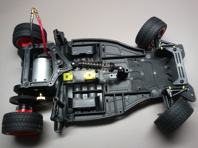
Image of smart car from Feescale (Courtsey: www.google.com)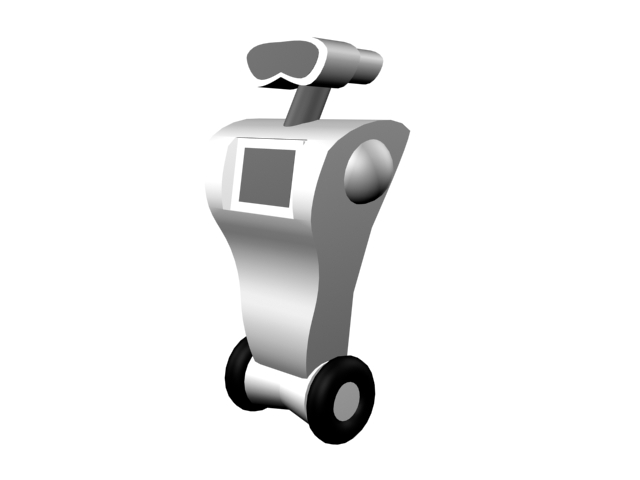
Self-balacing Robot (Courtsey: www.google.com (not ours))
What is this about???
    Self balancing structures are ideal example to prove the extend of applicability of embedded systems, ruggedness of control systems
and an example to handle real-time systems. From the embedded context, these type of projects are helpful in providing the designer a much
better insight about RTOS (real time operating systems), FPU (Floating point units) and the digital signal processing techniques.

     Here in this project we are targeting to self balance a smart car from M/s Freescale on its two rear wheels. This is a real time sys-
tem where we have to take decision on the go. This car on it's two wheel is unstable and won't be able to stand. Here we develop motor
driving electronics(Hardware), PID control, filtering techniques and RTOS(Software) as the part of the project.
Is there any Physics over there???
    Here the force which makes the system to unstable is the rotating torque in the direction of C.G (centre of gravity) shift. To compensate
this we move the wheels in a direction which counter balance the torque from C.G. i.e the net torque makes the system stable at the desired angle.
How we balance the system!!!!
How does control system work???
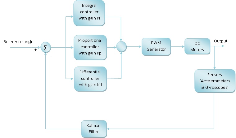
This is how we implemented Control System
Hardware Requirement
- Structure/Chasis of Car ———————————————————> 1Nos
- DC-Motor (Preferably 5A motor) ————————————————–> 2Nos
- Battery (7.2V, 1A) ————————————————————–> 1Nos
- Tiva launch pad board (for TM4C123GXL) ——————————————> 1Nos
- Sensor hub Booster pack for launch pad ——————————————> 1Nos
- Motor driver L298 Board or IC (Board is preferred) ——————————> 2Nos
- Wheels for Car ——————————————————————> 2Nos
- Switches (for ON/OFF) (We used SPDT swich) ————————————–> 1Nos
- 7805 (For generating 5V) (Procured associated capacitors also) —————–> 1Nos
- 10uF, 0.1uF capcitors —————————————————– –> 10Nos (Aprrox)
What we tried to do!!!!
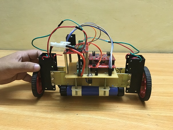
We have started with the smart car from M/s Freescale. We build a powering platform for TIVA launch pad. The platform contains the 3.3V generator for TIVA, Motor driver circuitry based on L298 IC.The image of the platform mounted on car is shown below.
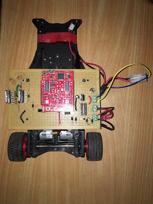
Smart carready to stand up!!!!
A simple systick based OS is implemented in the TIVA launchpad board. As a starting point we considered only the accelerometer as the sensor. We also implemented a simple PID controller. During the testing of this configuration, we found that the controller is not able to stabilize.
Then we have decided to change the platform to a new car (Here we doubted whether the platform is stabilizable or not). The structure of the new platform is as shown below.
New face of project!!!!
Here we decided to go with the previous code. Then we faced the same instability issue here also. With further literature survey and consultancy with Mr Arvind (DESE), we realized some mechanical adjustments on the system has to be done. Especially on the position of battery. We also realized that accelerometer reading is not the best choice for the bodies in motion like this project. This is due to the sensor noise in the accelerometer. Hence we decided to take gyroscope data also. Here involves the the data fusion of accelerometer and gyroscope. This also calls for the filtering to reduce the noise.
The options for filtering were
- Kalman filter (KF)
Please refer the following link for better understanding of KF [1]
- Complimentary filter (CF)
Please refer the following link for better understanding of CF [2] [3]
With these modifications we felt that the system is stabilizable. After this we started tuning the gains of PID controller. The gains were tuned by following nichols ziegler method [4].
Then we found that the system is stable!!!!!!!!!!!!!!!!!!!!!.
How Software works???
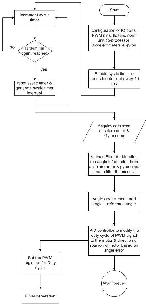
Software Flowchart
Finally this one stands!!!!!!!!!
Self Balancing Video
(B) LINE FOLLOWER USING FREESCALE LINE SCAN CAMERA
Understanding the line scan camera
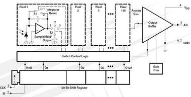
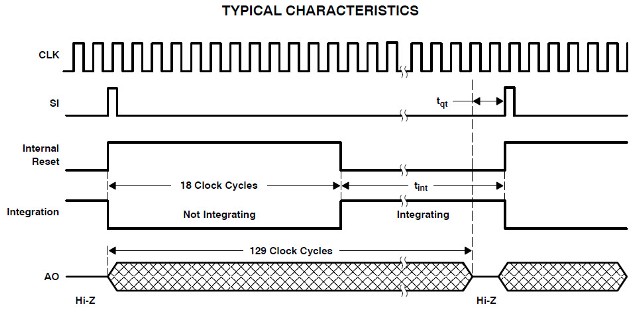
    The sensor consists of 128 photodiodes arranged in a linear array. Light energy impinging on a photodiode
generates photocurrent, which is integrated by the active integration circuitry associated with that pixel.

During the integration period, a sampling capacitor connects to the output of the integrator through an analog
switch. The amount of charge accumulated at each pixel is directly proportional to the light intensity and the
integration time.

The output and reset of the integrators is controlled by a 128-bit shift register and reset logic. An output cycle
is initiated by clocking in a logic 1 on SI. For proper operation, after meeting the minimum hold time condition,
SI must go low before the next rising edge of the clock. An internal signal, called Hold, is generated from the
rising edge of SI and transmitted to analog switches in the pixel circuit. This causes all 128 sampling capacitors
to be disconnected from their respective integrators and starts an integrator reset period. As the SI pulse is
clocked through the shift register, the charge stored on the sampling capacitors is sequentially connected to a
charge-coupled output amplifier that generates a voltage on analog output AO. Simultaneously, during the first
18 clock cycles, all pixel integrators are reset, and the next integration cycle begins on the 19 th clock. On the
129 th clock rising edge, the SI pulse is clocked out of the shift register and the analog output AO assumes a
high impedance state. Note that this 129 th clock pulse is required to terminate the output of the 128 th pixel, and
return the internal logic to a known state. If a minimum integration time is desired, the next SI pulse may be
presented after a minimum delay of t qt (pixel charge transfer time) after the 129 th clock pulse.

AO is an op amp-type output that does not require an external pull-down resistor. This design allows a rail-to-rail
output voltage swing. With V DD = 5 V, the output is nominally 0 V for no light input, 2 V for normal white level, and 4.8 V
for saturation light level. When the device is not in the output phase, AO is in a high-impedance state.
Functional Block Diagram
PRINCIPLES OF OPERATION
   The integration time of the linear array is the period during which light is sampled and charge accumulates on
each pixel’s integrating capacitor.

The integration time is the time between the SI (Start Integration) positive pulse and the HOLD positive pulse
minus the 18 setup clocks.

Each pixel of the linear array consists of a light-sensitive photodiode. The photodiode converts light intensity
to a voltage. The voltage is sampled on the Sampling Capacitor by closing switch S2 (position 1) (see the
Functional Block Diagram on page 1). Logic controls the resetting of the Integrating Capacitor to zero by closing
switch S1 (position 2).

At SI input, all of the pixel voltages are simultaneously scanned and held by moving S2 to position 2 for all pixels.
During this event, S2 for pixel 1 is in position 3. This makes the voltage of pixel 1 available on the analog output.
On the next clock, S2 for pixel 1 is put into position 2 and S2 for pixel 2 is put into position 3 so that the voltage
of pixel 2 is available on the output.
Following the SI pulse and the next 17 clocks after the SI pulse is applied, the S1 switch for all pixels remains
in position 2 to reset (zero out) the integrating capacitor so that it is ready to begin the next integration cycle.
On the rising edge of the 19 th clock, the S1 switch for all the pixels is put into position 1 and all of the pixels begin
a new integration cycle.

The first 18 pixel voltages are output during the time the integrating capacitor is being reset. On the 19 th clock
following an SI pulse, pixels 1 through 18 have switch S2 in position 1 so that the sampling capacitor can begin
storing charge. For the period from the 19 th clock through the n th clock, S2 is put into position 3 to read the output
voltage during the n th clock. On the next clock the previous pixel S2 switch is put into position 1 to start sampling
the integrating capacitor voltage.
PARAMETER MEASUREMENT INFORMATION
For normal operation of the camera, the user needs to take care of the following signals only:
• CK (clock)
• SI (serial input)
• AO (analog output)
where CK and SI are camera inputs and AO is a camera output.
These three signals (CK, SI, and AO) are synchronized, so the SI and CK signals will be adjusted to start the
camera operation correctly:
1. Both signals must have the same pulse width
2. Both must be perfectly aligned out of phase for half pulse
3. As a result, AO signal will be perfectly aligned with CK.
Demonstration of line follower
We have divided the output array into five sections.
| Far left | Left | Center | Right | Far Right |
 1             2      3        4        5
If it does not fall into any of these bins we give it code 0.
(C) Integration of part (A) and (B) in Free RTOS
We have implemented the self-balancing and line following as two separate tasks in freeRTOS.
The Application 1 directly gets the data from IMU sensor and gives it to Timer Controller which in turn gives it to Motor Driver.
And the Application 2 directly gets from line scan camera ,firnd the direction of movement and gives it to Application 1.
Teh Command Manger is not controlling the flow of data . That is to be done and is explained in future scope.
Future scope
The below diagram shows the control flow.
The command manager is the heart of the freeRTOS system.
Application 1 (control loop) will request command manager for sensor data.
The command manager will forward this request with task id and request id to IMU sensor ,which in turn will reply with the sensor data along
with the request id.
Now , the command manager replies to application 1 with the sensor data.

Application 1 uses the received data to set PWM width to set the motors.
Similar is the communication between Application 2 and command manager.
It requests for line scan camera data and command manager gets the data from line camera and gives it to  Application 2 which decides the
direction of motion and sends actuation command to Application 1 .
General message format maintained by Command manager
{
 task id
 request id
 buffer start address
 length of the buffer
}
Issues Faced
  The output of line scan camera was quite varying with the light intensity,so the decision part becomes critical .
  The bot is not stable for a longer time ,so it becomes very difficult to get to a decision in that short time.
References
Introduction toi line scan camera
Working Description of Line scan camera
Team members
Sethu Mathavan
Anjali Shukla
Recent Comments