REMOTE SAFETY MONITORING IN CONFINED SPACE
Objective:
To detect the fall of a person along with monitoring his/her BPM and wirelessly
transmit the message on the terminal to ensure that the person has not fallen unconsciously.
Motivation:
Working in Confined Space for anyone is very risky to life but for doing
maintenance activities workers has to go to these confined spaces. Confined space is an
enclosed space with restricted entry and exit. It is associated with many hazards like toxic
atmosphere, oxygen deficiency and excessive heat. Due to all these conditions the person
working in the confined space may become unconscious and if left unattended then it might
result in loss of life.
Requirements
•Hardware Requirements
•TIVA TM4C123GH6PM microcontroller
•BOOSTXL-SENSHUB Sensor Hub Booster Pack
•Pulse Rate Sensor
•Two Xbee S2 modules
•Two 9V / 12V Adapters
•USB to RS232 Converter
•Jumper Wires
•Software Requirements
•Code Composer Studio
•XCTU
•Tera Term

Interfacing of Sensor Hub with TM4C123GHPM

•Required interconnections:
•PB2 – J2.2 (Interrupt)
•PD0 – J2.7 (I2C3 SCL)
•PD1 – J2.6 (I2C3 SDA)
•3.3V – J1.1
•GND – J2.1

Interfacing of Pulse Sensor with Tiva board TM4C123GHPM
•Pin-1(GND): It is connected to GND pin on tivaboard.
•Pin-2(VCC): It is connected to the VBUS pin on tivaboard.
•Pin-3(Signal): It is connected to PE4(configured it to analog).

TM4C123GHPM ADC Configuration and Initialization Steps:
Enable the ADC module.
Configure the pin to be used as ADC input.
Configure the trigger source and priority of sample sequencer.
Configure the sample sequencer to capture the value of channel when trigger
occurs.
Enable the sample sequencer.
Clear the sample sequencer interrupt so that it no longer asserts.
Read the value of ADC.
Interfacing of Xbee S2 RF module with Tiva board TM4C123GHPM

Software Configuration of Xbee module
•To configure XBee in either operating mode and device function type, Digi International
provides a software tool known as X-CTU.
•First connect both XBee devices to PC/Laptop serial port using XBee USB adapter & cable. Now
open X-CTU software and click on (+) symbol in upper left-hand side to add device.
•The Add radio device window will pop up in which we need to select USB port to which we
have attached XBee devices. Set the baud rate 115200 and the values of data bits, parity
and stop bits.
•Do same procedure to add second XBee device.
•Now both devices will appear in upper left corner of X-CTU and their parameter value at right
hand side.
•Click on update to update the firmware by selecting the proper family, function and version.
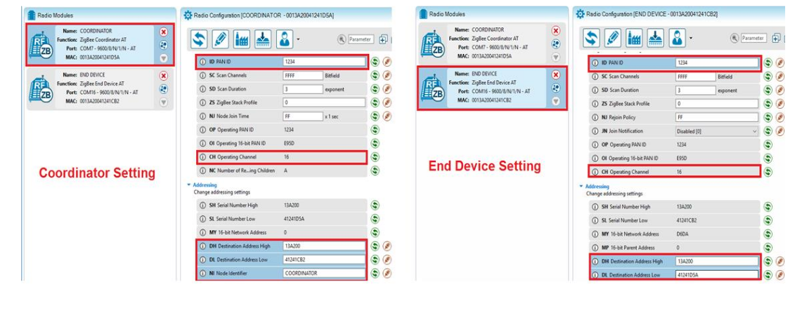
•After updating XBee devices with correct firmware, we must ensure at least three parameters
of XBee devices given below
•Baud rate should be same for each device.
•PAN ID should be unique for all XBee devices in same n/w.
•Operating Channel should be same for all devices in same n/w.
• To test the communication, open the console.

Fall Detection Algorithm
•The fall detection algorithm is based on the recognition of impact and posture phases of the
falls, which can be achieved by threshold comparisons of some features.
•The RMS of acceleration displays distinctive change in the impact phase of the fall. When
RMS exceeded the acceleration threshold for impact (Ati), the impact phase is detected.
•If the absolute value of roll or pitch exceeds Otp within Ttp after the impact phase (the time
threshold for posture), the posture phase is detected.
•After the recognition of the impact and posture phases, a fall of the human body is inferred.


BPM (Beats Per Minute) Determination Algorithm
•The value of the signal generated by the sensor goes above and below a nominal value
whenever it detects a heartbeat.
•The average and standard deviation of the signals generated by the sensor were observed
in each of the 2 cases:
•when the sensor was not touched.
•when the sensor was touched.
•An array of size 75 was used to calculate the heart rate with a latency of 30 sec and a
throughput of 200ms.
•Thus, 75 samples were collected every 30 sec and stored in the array in a circular fashion.
•Samples which were above the predetermined threshold were counted as a beat and the
number of beats in the previous 30 sec were calculated.
•This was multiplied by 2 to get the bpm.
Unconsciousness Detection Algorithm

Challenges Faced:
1. Interfacing of sense hub with Tiva board was not direct mounting but it required few
other connections to carry out.
2. Installation of USB to RS232 driver.
3. We have tried hard to subtract gravitational component from each axis to get linear
acceleration efficiently. But it was not very much accurate as during the still position
also the rms value of acceleration was 0.01m/s^2. Hence a slight movement was
causing the accelerometer drift.
4. To get the change in the orientation initially we were taking all the three Euler angles (roll,
pitch and yaw) but after doing many experiments we realised that to detect the change in
orientation in case of fall the absolute value of change in roll and pitch is sufficient.
5. Calculating bpm using pulse sensor data was also bit challenging. Although still the bpm is
not 100% accurate as the data was highly noisy and it required precise press on the led to
get the meaningful data which can be counted as a pulse detected.
Future scope:
1. Data of Fall detection can be used to trigger the mechanism of Fall protection.
2. To make a Centralized Confined Space Monitoring System one can integrate gas detector to
monitor the presence of hazardous gases and a full duplex intercom system for
communication between the worker doing job in confined space and the helper.
References:
[1]. BOOSTXL-SENSHUB Sensor Hub Booster Pack Getting Started Guide.
[2]. Tiva TM4C123GH6PM Datasheet.
[3]. Position and Orientation determination thesis by Charlotte Treffers and Wietmarschen.
[4]. Sensor Based System for Human Fall Monitoring by Aihua, Xuendong, Yinan and Jie.
[5]. https://www.electronicwings.com/sensors-modules/xbee-module
[6]. Pulse Sensor Getting Started Guide.

Recent Comments