
ES1 Mini-project :Gesture Controlled Car Team Members
- Sharda Prasad Agrawal
- Nirmal Mohan
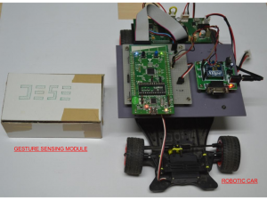
The aim of the mini-project is to make a gesture controlled car that moves left,right, forward or backward based on the hand gestures. Basically the gesture actually here is the tilt of the hand with respect to the vertical in both X and Y axes. There are two parts to this project. The first is the gesture sensing module that is actually an accelerometer and then there is the steerable robotic car (having onboard the Discovery 32L ARM CM3 based Evaluation Kit).
The following components are required
- 1. Accelerometer (3 axis) – ADXL335 – 1
- 2. LM324 (Quad Op-amp) – 1
- 3. Encoder-Decoder IC (HT12D ,HT12E) – 1 pair
- 4. RF Transmitter-Receiver Pair – 1 pair
- 5. Discovery 32L Board – 1
- 6. Motor Driver IC – L293D – 1
- 7. DC Motor – 2
- 8. Toy Car Chassis – 1
- 9. General Purpose PCB – 2
- 10. Battery (9 V) – 1
- 11. Linear Regulator 7805 – 2
- 12. Resistors and capacitors —
There are two electronic modules in the circuit
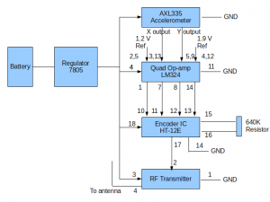
- 1. The gesture detection circuit
It consists of a accelerometer, encoder IC and RF transmitter. It is battery powered using a 9V battery and a 5V regulator 7805. It is intended to be hand held.
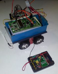
- 2. The motor controlling circuit
It consists of RF receiver, decoder IC , STM32L Discovery Board, L293D IC and the pair of DC motors. All these electronics are mounted on the car and powered by a 7.5 V Li Ion Battery.
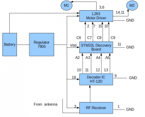
The complete block diagram is shown below.
The accelerometer module is intended to be hand held. There are six commands
- 1. Forward – The hand will be tilted forward
- 2. Backwards – The hand will be tilted upwards
- 3. Sharp Left – The hand will be tilted left
- 4. Sharp Right – The hand will be tilted right
- 5. Gentle Left – The hand will be tilted left and forward
- 6. Gentle Right- The hand will be tilted right and forward
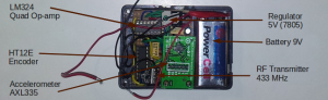
The electronics for the gesture controlling module is shown in the figure below.
The gesture detection electronics is shown below.
The robotic car will have two motors driving the left and the right sides. They will be controlled by the GPIO pins of the Discovery 32L module. The motor driver ICs L293D is used to driving the motor. By using driving the inputs of the L293D to “1””0″ the motor is driven forward by driving the input “0” “1” we have the motor running in the reverse direction. The sense of motor rotation for the left and the right wheels depend on the input from the RF link. The block diagram is given below.
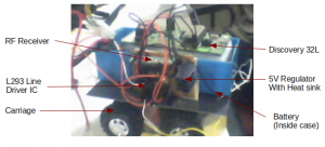
The Regulator, RF receiver, decoder IC and the general purpose board is mounted on the general purpose board. The output 5V of the same regulator is used to power the Discovery 32L board also. As the regulator was heating up we used a heat sink for it.The picture showing the various parts of the carriage is given below.
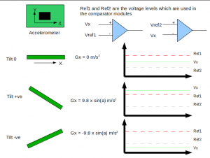
The theory of operation of the gesture detection circuit is shown in the figure below.
Recent Comments