
| OVERVIEW | GPIO PINS | GPTM INT | SAMPLE | TASKS |
In TI Tiva micro controllers, the timers are called General-Purpose Timer Module (GPTM). The General-Purpose Timer Module (GPTM) contains six 16/32-bit GPTM blocks and six 32/64-bit Wide GPTM blocks. In otherwords, there are 12 Timer Blocks in the TI Tiva TM4C123G, 6 of them are 16/32-bit timers and the other 6 are 32/64-bit. Each 16/32-bit GPTM block can provide two 16-bit (half-width) timers/counters that are referred to as Timer A and Timer B. These timers/counters can be further configured to operate independently as timers or event counters, or concatenated together to operate as one 32-bit (full-width) timer or one 32-bit Real-Time Clock (RTC).
Similarly, each 32/64-bit Wide GPTM block provides two 32-bit timers, also called Timer A and Timer B, and they can be concatenated together to form a 64-bit timer. Timers can also be used to trigger μDMA transfers. All timers have interrupt controls and separate interrupt vectors as well as separate interrupt handlers.
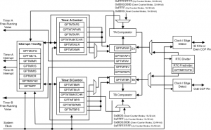
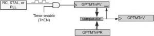
Figure: GPTM Module Block Diagram
The 16/32-bit timer blocks are designated as Timer 0, Timer 1, …, and Timer 5. The following shows the base addresses for the 16/32-bit Timer blocks:
- 16/32-bit Timer 0 base: 0x4003.0000
- 16/32-bit Timer 1 base: 0x4003.1000
- 16/32-bit Timer 2 base: 0x4003.2000
- 16/32-bit Timer 3 base: 0x4003.3000
- 16/32-bit Timer 4 base: 0x4003.4000
- 16/32-bit Timer 5 base: 0x4003.5000
- 32/64-bit Wide Timer 0: 0x4003.6000
- 32/64-bit Wide Timer 1: 0x4003.7000
- 32/64-bit Wide Timer 2: 0x4004.C000
- 32/64-bit Wide Timer 3: 0x4004.D000
- 32/64-bit Wide Timer 4: 0x4004.E000
- 32/64-bit Wide Timer 5: 0x4004.F000
Timer A and Timer B
Each of the Timer blocks contains two timers. They are called Timer A and Timer B. These two timers A and B can work independent of each other as two 16-bit timers or together as one single 32-bit timer. TimerA and TimerB each contains a counter. When the clock is fed to them, they keep counting up/down. We can read their contents as they count and we can load a new value in them. We will examine TimerA and give some examples. The discussion about TimerA also applies equally to TimerB. First, we must remember that, we need to enable the clock to the Timers before they can be used. This is done with the RCGCTimer register.
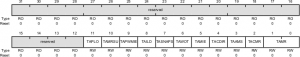
RCGCTimer
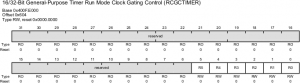
| Bit | Name | Description |
|---|---|---|
| 0 | R0 | Timer0 clock control (0: clock disabled, 1: clock enabled) |
| 1 | R1 | Timer1 clock control (0: clock disabled, 1: clock enabled) |
| 2 | R2 | Timer2 clock control (0: clock disabled, 1: clock enabled) |
| 3 | R3 | Timer3 clock control (0: clock disabled, 1: clock enabled) |
| 4 | R4 | Timer4 clock control (0: clock disabled, 1: clock enabled) |
| 5 | R5 | Timer5 clock control (0: clock disabled, 1: clock enabled) |
The RCGCTIMER is part of the System Control registers. We must enable the clock to Timer0 – Timer5 before we can use them. Notice, in RCGCTIMER registers, bit R0 is for Timer0 block, bit R1 is for Timer1 block, and so on.
Timers Register Map
| Name | Offset | Tivaware Name | Description |
|---|---|---|---|
| GPTMCFG | 0x000 | TIMERn_CFG_R | GPTM Configuration |
| GPTMTAMR | 0x004 | TIMERn_TAMR_R | GPTM Timer A Mode |
| GPTMTBMR | 0x008 | TIMERn_TBMR_R | GPTM Timer B Mode |
| GPTMCTL | 0x00C | TIMERn_CTL_R | GPTM Control |
| GPTMSYNC | 0x010 | TIMERn_SYNC_R | GPTM Synchronize |
| GPTMIMR | 0x018 | TIMERn_IMR_R | GPTM Interrupt Mask |
| GPTMRIS | 0x01C | TIMERn_RIS_R | GPTM Raw Interrupt Status |
| GPTMMIS | 0x020 | TIMERn_MIS_R | GPTM Masked Interrupt Status |
| GPTMICR | 0x024 | TIMERn_ICR_R | GPTM Interrupt Clear |
| GPTMTAILR | 0x028 | TIMERn_TAILR_R | GPTM Timer A Interval Load |
| GPTMTBILR | 0x02C | TIMERn_TBILR_R | GPTM Timer B Interval Load |
| GPTMTAMATCHR | 0x030 | TIMERn_TAMATCHR_R | GPTM Timer A Match |
| GPTMTBMATCHR | 0x034 | TIMERn_TBMATCHR_R | GPTM Timer B Match |
| GPTMTAPR | 0x038 | TIMERn_TAPR_R | GPTM Timer A Prescale |
| GPTMTBPR | 0x03C | TIMERn_TBPR_R | GPTM Timer B Prescale |
| GPTMTAPMR | 0x040 | TIMERn_TAPMR_R | GPTM TimerA Prescale Match |
| GPTMTBPMR | 0x044 | TIMERn_TBPMR_R | GPTM TimerB Prescale Match |
| GPTMTAR | 0x048 | TIMERn_TAR_R | GPTM Timer A |
| GPTMTBR | 0x4C | TIMERn_TBR_R | GPTM Timer B |
| GPTMTAV | 0x050 | TIMERn_TAV_R | GPTM Timer A Value |
| GPTMTBV | 0x054 | TIMERn_TBV_R | GPTM Timer B Value |
| GPTMRTCPD | 0x058 | TIMERn_RTCPD_R | GPTM RTC Predivide |
| GPTMTAPS | 0x05C | TIMERn_TAPS_R | GPTM Timer A Prescale Snapshot |
| GPTMTBPS | 0x060 | TIMERn_TBPS_R | GPTM Timer B Prescale Snapshot |
| GPTMTAPV | 0x064 | TIMERn_TAPV_R | GPTM Timer A Prescale Value |
| GPTMTBPV | 0x068 | TIMERn_TBPV_R | GPTM Timer B Prescale Value |
| Where n = 0 to 5 |
Each GPTM block is composed of different control and status registers and these control and status registers can be divided into six groups based on their functions. We only discuss those registers used for the TimerA since the same registers are used for the TimerB. These registers can be divided into the following groups:
- TimerA Control Register group
- TimerA Status Register group
- Timers A and B Interrupt and Configuration Register group
- External Controls group
TimerA Control Register Group
Eight registers are used to configure and control the operations of the Timer A:
- GPTM Configuration Register (GPTMCFG)
- GPTM Control Register (GPTMCTL)
- GPTM Timer A Mode Register (GPTMTAMR)
- GPTM Timer A Interval Load Register (GPTMTAILR)
- GPTM Timer A Match Register (GPTMTAMATCHR)
- GPTM Timer A Prescale Register (GPTMTAPR)
- GPTM Timer A Prescale Match Register (GPTMTAPMR)
- GPTM Timer A Prescale Snapshot Register (GPTMTAPS)
GPTM Control Register (GPTMCTL)
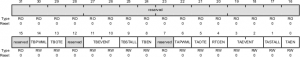
| Bit(s) | Name | Description |
|---|---|---|
| 0 | TAEN | Timer A Enable 0: disabled 1: enabled |
| 1 | TASTALL | Timer A Stall (useful while debugging) 0: Timer A continues counting if the CPU is halted by the debugger, 1: Timer A Stalls (stops counting) while the CPU is halted by the debugger. |
| 2 & 3 | TAEVENT | Timer A Event Mode 0: positive edge 1: negative edge 2: reserved 3: both edges |
| 4 | RTCEN | RTC Stall Enable (useful while debugging) 0: RTC Stalls (stops counting) while the CPU is halted by the debugger 1: RTC continues counting if the CPU is halted by the debugger. |
| 5 | TAOTE | Timer A Output Trigger Enable 0: ADC trigger disabled 1: ADC trigger enabled |
| 6 | TAPWML | GPTM Timer A PWM Output Level 0: Output is unaffected 1: Output is inverted |
| 8 | TBEN | GPTM Timer B Enable 0: Timer B is disabled 1: Timer B is enabled. |
| 9 | TBSTALL | GPTM Timer B Stall Enable 0: Timer B continues counting while the processor is halted by the debugger 1: Timer B freezes counting while the processor is halted by the debug |
| 11 & 10 | TBEVENT | GPTM Timer B Event Mode 0x0: Positive going edge 0x1: Negative going edge 0x3: Both edges 0x2: Reserved. |
| 13 | TBOTE | GPTM Timer B Output Trigger Enable 0: The output Timer B ADC trigger is disabled 1: The output Timer B ADC trigger is enabled. |
| 14 | TBPWML | GPTM Timer B PWM Output Level 0: Output is unaffected 1: Output is inverted. |
| 31:15 | Reserved | Reserved |
Note:
- During the initialization of the Timers we must disable them. Modifying the configurations of a running timer may cause unpredictable results.
- We use bit D0 of GPTMCTL (GPTM Control) register to disable or enable the TimerA.
GPTM Configuration Register (GPTMCFG)
To configure TimerA as 16- or 32-bit, we must use GPTMCFG (GPTM Configuration) register. Bits D2, D1, and D0 are used to select either 16- or 32-bit option. To use the 16-bit option we need to have D2:D1:D0=0x4. As mentioned above, in 16-bit mode, TimerA and TimerB make two separate timers which work independently.
| D2:D1:D0 | Mode |
|---|---|
| 000 | 32-bit Mode |
| 001 | RTC Counter |
| 100 | 16-bit Mode |
TimerA Mode selection register (GPTMTAMR)
The mode selection such as periodic, count up/down selection for TimerA is done with GPTM TimerA Mode (GPTMTAMR) register.
| Bit(s) | Name | Description |
|---|---|---|
| 0 & 1 | TAMR | Timer A Mode |
| 2 | TACMR | Timer A Capture Mode (0: Edge Count, 1: Edge Time) |
| 3 | TAAMS | Timer A Alternate Mode Select (0: Capture or Compare Mode, 1: PWM Mode) |
| 4 | TACDIR | Timer A Count Direction (0: Count Down, 1: Count Up) |
| 5 | TAMIE | Timer A Match Interrupt Enable (0: the match interrupt is disabled, 1: enabled) |
| 6 | TAWOT | Timer A Wait-On-Trigger (0: It begins counting when enabled, 1: waits for trigger) |
| 7 | TASNAPS | Timer A Snap-Shot Mode (0: Snap Shot is disabled) |
| 8 | TAILD | Timer A Interval Load Write |
| 9 | TAPWMIE | Timer A PWM Interrupt Enable (0: Capture Event Interrupt is Disabled, 1: Enabled) |
| 10 | TAMRSU | Timer A Match Register Update |
| 11 | TAPLO | Timer A PWM Legacy Operation |
The mode selection is done with D1:D0 bits of GPTMTAMR, as shown below:
| Mode | D1 | D0 | Mode Name |
|---|---|---|---|
| 0 | 0 | 0 | Reserved |
| 1 | 0 | 1 | One-Shot Mode |
| 2 | 1 | 0 | Periodic Mode |
| 3 | 1 | 1 | Capture Mode |
The direction Count is done with D4 (TACDIR). Upon Reset, the default is down counter. By making D4=1, TimerA counts up.
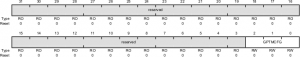
GPTM Timer n Interval Load (GPTMTnILR)
When the timer is counting down (the timer counts down if the TACDIR bit of the GPTMTAMR register is 0), the timer counter begins counting from GPTMTnILR (GPTMTAILR / GPTMTBILR) and goes down until it reaches zero. Then, the timer counter is reloaded with the value from GPTMTnILR and the TnTORIS flag of the GPTMRIS register is set.
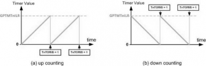
When the timer is counting up, the timer counter begins counting from 0 and goes up until it reaches the GPTMTnILR value. Then, the timer counter is cleared to zero and the TnTORIS flag of the GPTMRIS register is set.
Upon reset, all bits of the GPTMTnILR register are initialized to 1s which makes the biggest value and has no effect on the timer counting. But the software can change the value of GPTMTnILR. The smaller values for the register leads the timer timeout faster and the TnTORIS flag sets sooner. In other words, changes of delay can be made by setting the GPTMTnILR register and monitoring the TnTORIS flag.
Timer A Status Register Group
Three registers are used to monitor and detect the status of the Timer A:
- GPTM Timer A Register (GPTMTAR)
- GPTM Timer A Value Register (GPTMTAV)
- GPTM Timer A Prescale Value Register (GPTMTAPV).
GPTMTnV (GPTM Timer Value)
GPTMTAV and GPTMTBV are two 16-bit up/down counter registers. When a timer is in 16-bit mode, they work as 2 separate counters. When the timer is in 32-bit mode, they are cascaded to form a 32-bit counter. When read, this register shows the current, free-running value of Timer A in all modes. When written, the value written into this register is loaded into the GPTMTAR register on the next clock cycle.
Note: In 16-bit mode, only the lower 16-bits of the GPTMTAV register can be written with a new value. Writes to the prescaler bits have no effect.
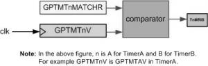
GPTM TimerA Match Register (GPTMTAMATCHR)
The GPTM Timer A Match (GPTMTAMATCHR) register can be used to load a match value, and this value can be compared with the current timer value stored in the GPTM Timer A (GPTMTAR ) register to trigger a matching interrupt or set a flag to indicate that a time value matching has occurred if both values are equal. The GPTM Timer B has the similar registers and functions.
When TimerA keeps counting it is compared with the contents of this register. Whenever the contents of free-running TimerA counter and TimerA Match register are equal, the TAMRIS Flag goes up indicating there is a match. The D4 of GPTMRIS register belongs to this flag.
Note: Although the TimerA Match is a 32-bit register, only the lower 16 bits are used in the 16-bit configuration selection.
GPTM Timer A Register (GPTMTAR)
- This is a 32-bit register and all 32 bits are used to indicate the current value of the 16-bit free-running counter of the Timer A. This register shows the current value of the Timer A counter in all cases except for Input Edge Count and Input Edge Time modes.
- In the Input Edge Count mode, this register contains the number of edges that have occurred. In the Input Edge Time mode, this register contains the time at which the last edge event took place.
- In the 16-bit Input Edge Count, Input Edge Time, and PWM modes, bits 15:0 contain the value of the counter and bits 23:16 contain the value of the prescaler, which is the upper 8 bits of the count. Bits 31:24 always read as 0.
- When a 16/32-bit GPTM is configured to one of the 32-bit modes, GPTMTAR works as a 32-bit register with the upper 16 bits corresponding to the contents of the GPTMTBR register.
- To read the value of the prescaler in 16-bit One-Shot and Periodic modes, read bits [23:16] in the GPTMTAV register. To read the value of the prescalar in periodic snapshot mode, read the Timer A Prescale Snapshot (GPTMTAPS) register.
GPTM Raw Interrupt Status Register (GPTMRIS)
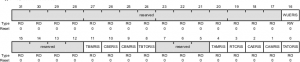
This 32-bit register only used the lower 16 bits to monitor and set a raw or internal interrupt if a GPTM-related raw interrupt occurred. These bits are set whether or not the interrupt is masked in the GPTMIMR register. However, whether these set raw interrupts can be sent to the interrupt controller to be further processed, it depends on whether the corresponding bits on the GPTMIMR register are set (enabled) or not (disabled). Only for those bits that have been set on the GPTMIMR register, they can be sent to the NVIC. The bit field and functions for this register are similar to those in the GPTMIMR register. If a GPTM-related raw interrupt is generated, the corresponding bit on this register is set to 1. Each bit can be cleared by writing a 1 to its corresponding bit in GPTMICR register.
| Bit | Name | Description |
|---|---|---|
| 0 | TATORIS | Timer A Time-out Raw interrupt (0: not occurred, 1: occurred) |
| 1 | CAMRIS | Timer A Capture Mode Match Raw Interrupt (0: not occurred, 1: occurred) |
| 2 | CAERIS | Timer A Capture Mode Event Raw Interrupt (0: not occurred, 1: occurred) |
| 3 | RTCRIS | RTC Raw Interrupt(0: not occurred, 1: occurred) |
| 4 | TAMRIS | Timer A Match Raw Interrupt |
| 8 | TBTORIS | Timer B Time-out Raw interrupt (0: not occurred, 1: occurred) |
| 9 | CBMRIS | Timer B Capture Mode Match Raw Interrupt (0: not occurred, 1: occurred) |
| 10 | CBERIS | Timer B Capture Mode Event Raw Interrupt (0: not occurred, 1: occurred) |
| 11 | TBMRIS | Timer B Match Raw Interrupt |
| 16 | WUERIS | 32/64-Bit Wide GPTM Write Update Error Raw Interrupt Status |
Periodic mode vs. one shot mode
The timer can be in 4 different modes including the periodic and one shot modes. In periodic mode the timer continues counting after each timeout. But in one shot mode, the timer stops counting after timeout is reached. For example, when it is in up counting and one shot modes, it counts from 0 to GPTMTnILR and then goes to zero just once and then the TnEN bit of GPTMCTL is cleared causing the timer to stop.
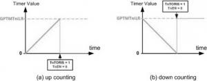
Figure 8.4: Counting in One Shot Mode
Each timer module has:
- A clock enable bit, SYSCTL_RCGCTIMER_R
- A control register, TIMERn_CTL_R
- A configuration register, TIMERn_CFG_R
- A mode register, TIMERn_TAMR_R
- A 32-bit reload register, TIMERn_TAILR_R
- A resolution (prescale) register, TIMERn_TAPR_R
- An interrupt clear register, TIMERn_ICR_R
- An interrupt arm bit, TIMERn_IM_R
- A flag bit, TIMERn_RIS_R
( where n = 0 to 5)
Initialization and Configuration for One-Shot/Periodic Timer Mode
Perform the following operational steps to complete the initialization and configuration process for this mode:
- Disable the selected timer by clearing the TnEN bit in the GPTMCTL register (TIMERn_CTL_R).
- Initialize the GPTMCFG register to set up timer(s) as 16/32-bit timers (TIMERn_CFG_R).
- Configure the TnMR field in the GPTMTnMR (TIMERn_TAMR_R) register by writing
- 0x1 for one-shot mode.
- 0x2 for periodic mode.
- Optionally configure the TnSNAPS, TnWOT, TnMTE, and TnCDIR bits in the GPTMTnMR (TIMERn_TAMR_R) register to select whether to capture the value of the free-running timer at timeout, use an external trigger to start counting, configure an additional trigger or interrupt, and count-up or count-down operational mode.
- Load the start value (time up value) into the GPTMTnILR (TIMERn_TAILR_R) and the GPTMTnPR (TIMERn_TAPR_R, if prescaler is used) registers for the count-down (count-up) operations.
- If interrupts are required, set the appropriate bits in the GPTMIMR (TIMERn_IMR_R) register to enable the selected interrupt source.
- After these initializations and configurations done, set the TnEN bit in the GPTMCTL (TIMERn_CTL_R) register to enable the timer and start counting.
- If no interrupt is used, one can poll the GPTMRIS (TIMERn_RIS_R) register to check the appropriate bits and wait for the time event to occur. If an interrupt is used, put appropriate codes inside the interrupt handler to process the interrupt. In both cases, the status flags are cleared by writing a 1 to the appropriate bit of the GPTMICR (TIMERn_ICR_R) register.
In One-Shot mode, the timer stops counting after the timeout event. If the timer is configured as a periodic mode, the timer reloads the start value (time up value) and continues counting after the timeout event.
Prescaler register for Timer A
In the above example, the largest time delay that we can create is:
65535 × (1 / 16MHz) = 65535 × 62.5 nsec = 4.096 msec.
One way to create a longer time delay is to use the prescaler register. TimerA in 16-bit mode has an 8-bit prescaler register whose value can go from 0x00 to 0xFF. The 8-bit prescaler extends the 16-bit timer to 24-bit. The prescaler register allows system frequency to be divided by a value between 1 and 256 before it is fed to the TimerA. Note the prescaler can yield proper division only when the timer is configured as a down counter. As shown in Figure 8.5, the clock is divided by GPTMTnPR + 1.
For CPU Freq=16MHz calculate the largest delay size using
- 16-bit TimerA without prescaler and
- 16-bit TimerA with prescaler.
Solution:
1/16MHz = 62.5 nsec is period of clock pulses fed to CPU.
- 65,536 x 62.5 nsec = 4.096 msec for TimerA 16-bit option .
- 65,536 x 256 x 62.5ns = 1.0485 second for TimerA 16-bit option with the Prescaler.
Recent Comments