
PROBLEM STATEMENT
To measure AC Power using Tiva Microcontroller Board TM4C123GH6PM using the 12-bit conversion precision
ADCs which will convert our analog signal to digital signal for processing and then outputting the obtained
power, RMS value of voltage(Vrms) and RMS value of current(Irms) to the LED display panel.
WORKABLE SOLUTIONS:
| SOLUTION 1 | SOLUTION 2 |
| Using voltage transformer to get the voltage from 220V-12V and then using voltage divider circuit convert it to 3-4V range and then use a half wave rectifier so that we can give it to our Tiva Board |
Voltage measurement technique will be same i.e by employing the use of the step- down transformer(220v-12V AC). |
| For current measurement we can use a current sensor which will give output in the form of voltage and by using signal conditioning circuit we can feed that signal into the ADC port of the Tiva Board. Using both the ADC values we can calculate Power. |
For current measurement we can use Power Resistor of very low value (0.5-2 Ohms) and 50W rating. This will ensure that the drop across resistor is very less so that our operation will not be affected and at the same time we can find the current I using Ohm’s Law I= V/R. From ADC values we can get the power. |
THE PROTOTYPE
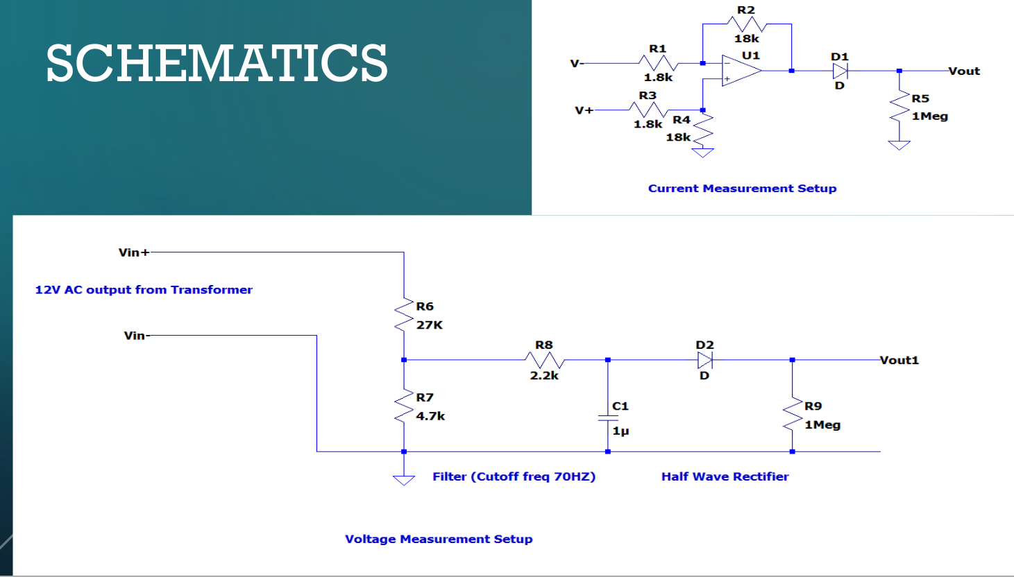
• For voltage measurement we are using a step-down transformer(220V-) which will give output in the range of 12V and by using voltage divider network we are converting it into
range of 4V and then using Half wave rectifier our voltage signal for giving to the Tiva Board is ready.
• For current measurement we have employed the use of Power Resistor of 0.5 Ohm having power rating of 50W which means that it will sustain current upto 10A without burning the
resistor. Now we have taken voltage across the resistor and given it as input to the Difference Amplifier having gain of 11 and after that the output is passed through a half
wave rectifier to get the final output which can then be given to the Tiva Board.
SOFTWARE IMPLEMENTATION
• Two ADCs (ADC0 and ADC1) is used to samples the signals at the rate of 250KSPS and after every 5000 samples new calculated value of Power is displayed on the LCD display
panel.
• Sample sequences have been initiated on multiple ADC modules simultaneously using the GSYNC and SYNCWAIT bits in the ADCPSSI register during the configuration of each ADC
module.
• In each iteration of the while loop ADC value of voltage and current is read then squared and then summed till 5000 samples are done and then by taking the square root of that
value and multiplying it by ADC Resolution(0.8mV) and corresponding gain factor we will get the value of Vrms and Irms. Then just by simply multiplying the values of Vrms and
Irms we will get the power.
SOFTWARE IMPLEMENTATION
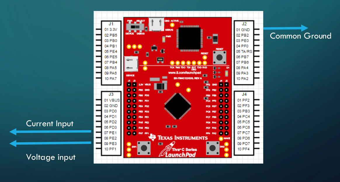
• ADC0 analog input channel on PE3 pin is used for sampling the Voltage signal.
• ADC1 analog input channel on PE1 pin is used for sampling the Current signal.
HARDWARE IMPLEMENTATION
• LM741 General Purpose OPAmp IC
• Step-Down Transformer (220V-12V) AC
• 1N4007 General Purpose Diode
• Power Resistor (0.5Ω)
• PCB Board
• Carbon Resistors(1.8K,18K,27k,4.7K)
FINAL RESULT
• For testing purpose we connected our circuit to 25W soldering rod and measured the output. The output came out to be around 26.12
with variance of ±0.3 W. This is fairly accurate given that there is also loading due to the current transformer connected to the same pin.
• We used the Power Resistor but for better accuracy we can use LEM sensor but they are expensive and for household voltages the setup
that we have designed is good to go.
Demo: power meter demo
Code:Powermeter
Recent Comments