
- INTRODUCTION
It is a small interesting game on a LCD screen. It is implemented in STR912 board using an accelerometer board as extra peripheral. In it a ball is moving up and down in an angle. It can be reflected back using a reflector at the bottom which can be controlled either by a JOY STICK or by TILTING THE BOARD.
- HARDWARE CONNECTION
Hardware connection diagram is shown below.
FIG 1 - : Hardware connection
The joy stick and NOKIA graphics LCD are STR912 on board peripherals. Joy stick side buttons are available as single analogue voltage signal and hence it is connected to an ADC. The centre button is available in a GPIO pin. Accelerometer has I2C interface. And we are making use of component of g(gravitational acceleration) on X – axis for detecting the tilt. LCD is interfaced using a 9 – bit SPI interface.
- SYSTEM SOFTWARE FLOW
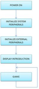
System software flow diagram
FIG 2 - : System software flow
System software flow is shown on the right side. After power on the system initializes the internal peripherals, which include SPI, TIMER, ADC and GPIOs. SPI is for LCD interfacing. Timer is for delay. ADC is for JOY STICK and GPIOs for software I2C to interface accelerometer.
Timer is set up for around 100mS and is used as a trigger for checking the inputs as well as for reading ADC values or Accelerometer readings. Accelerometer is setup for +/- 4g sensitivity and 25 conversions per second. SPI is running at 1 MHz clock and with 9 bit data width.
Then the initialization of external peripherals happens, which include NOKIA graphics LCD and Accelerometer board.
Next is display of introduction messages. And the game begins. Software flow for game is described below.
- SOFTWARE FLOW FOR THE GAME
Game software flow diagram is shown below.
FIG 3 - : Game software flow
At the beginning it displays “PRESS ENTER TO START”. Then it displays the CONTROL options ie.” G – CONTROL” for accelerometer control and “JOY STICK” for controlling using the joystick. According to the selected option, sets a variable named control. Now the timer flag is continuously checked and if set, clears the flag and reads the control input. According to the input moves the reflector position and displays it. Next moves the ball position. Also the boundaries for both are checked soon after incrementing position. Now the out condition is checked. If not out then updates the score and waits for timer flag. If out the score is displayed and when enter is pressed it goes to the beginning.
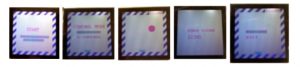
- HARDWARE SETUP
FIG 4 - : Hardware setup
- HOW TO PLAY?
- Step 1: After power on when the system is ready the LCD screen will show “PRESS ENTER TO START”.
Now press the enter key.ie Joy stick centre button.
- Step 2: After pressing the enter, the display will change to “CONTROL MODE”. Now we have two
options – “JOY STICK” and “G – CONTROL” or accelerometer. Active one will be in green back ground. Use JOY STICK UP and DOWN for changing option and press enter key.
- Step 3: Now the game starts. If the control option selected was joy stick use the JOY STICK LEFT and
RIGHT keys to move the reflector otherwise tilt the accelerometer board left and right .The score will be displayed at right top corner of the LCD.
- Step 4: Once you fail to reflect back the ball you will be OUT and the screen will display “YOUR SCORE”
and total score.Now press enter key to restart.
- Pause or Exit : If you want to pause or exit the game press enter key. The screen will show “RESUME”
and “EXIT”. Choose the option using JOY STICK UP and DOWN keys and press enter key. If you select “RESUME” the game will be resumed otherwise it will exit and display your score. Now press enter key to start a new game.
Recent Comments