
Problem
To create a line follower robot with no actual line.
Idea
The idea of the project is to develop a robot that follows any pattern drawn in GUI. The pattern collected from the GUI is sent wireless-ly, to the controller mounted on the car, using a Zigbee module. This pattern is then processed and used to drive the motors of the car.
Understanding The System

Components Required
| Sl. No | Component Name | Quantity |
|---|---|---|
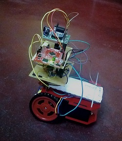
| 1 | Robotic Car | 1 |
| 2 | DC Motor | 2 |
| 3 | Battery (~8V,1A) | 1 |
| 4 | TM4C123GXL launch pad | 2 |
| 5 | Sensor Hub(booster pack) | 1 |
| 6 | Zigbee modules(Series 2) | 2 |
| 7 | Motor Driver IC (L298D) | 1 |
| 8 | Switches | 1 |
| 9 | 5V regulator IC and caps | 1 |
| 10 | 3.3V regulator IC | 1 |
Softwares Used
1. Eclipse for programming the Tiva board
2. OpenOCD for debugging
3. XCTU for configuring the Zigbee module
4. Netbeans IDE for developing GUI
Flow of Work
Configuring the Zigbee Module
We began the project by configuring the Zigbee modules using a software called XCTU[1]. For configuring the Zigbees, they should be programmed to do, both transmission and reception. One of the modules was configured as Coordinator and the other one as Router[2].
Developing GUI
We used a software called Netbeans[3], to develop the GUI. Our objective was to draw any pattern on the screen and then on the press of the button “START”, an array containing the relative angles of each pixel will be sent to the serial port. This data is then send to the transmitter Zigbee, using TIVA board as an interface.(For using TIVA as an interface, only 4 pins of the Zigbee module are required; VCC(pin1), pins 2 and 3 for data transmission, and GND(pin10).)
After this, we developed a GUI for drawing patterns and transmitting an array of angles relative to the previous position, following which we developed the hardware of the car. We went on to design the software for computing the pwm values given to the motor, corresponding to the angles. We also tried to implement feedback using a magnetometer, but the it turned out to be really noisy and affected the angle computation.
Tracing Path
Angle and distance information is transferred wireless-ly to the micro controller mounted on the vehicle. This information is processed to generate PWM signals to trace the path. Feedback control using magnetometer was inaccurate due to noise from magnetic field interferences.
Path Tracing Video
Recent Comments