
INTRODUCTION
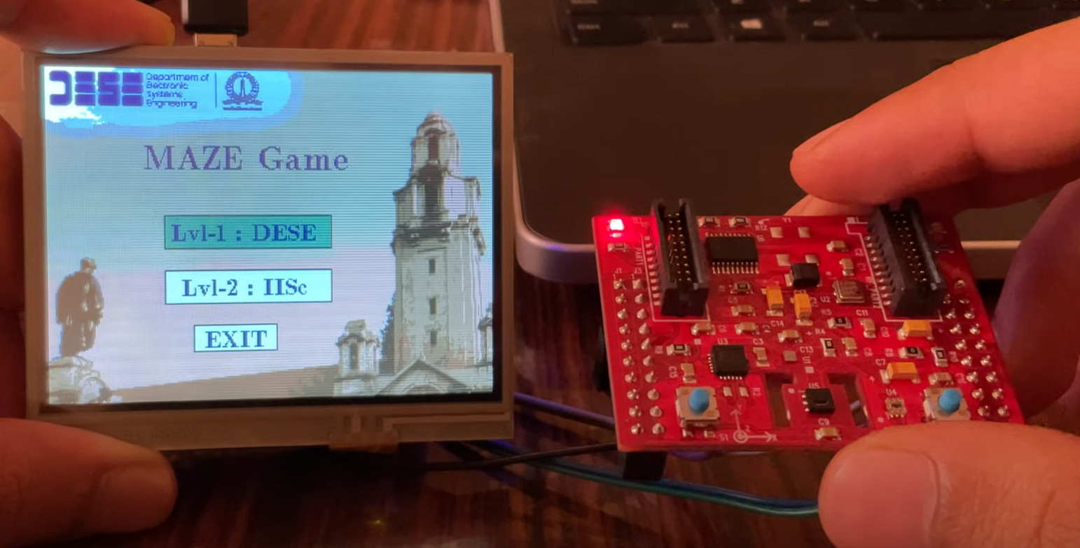
In this MINI project, we plan to make a maze game that uses the touch LCD (mounted with launchpad board) and SensorHub (connected using jumper wires). The Graphics Display uses SPI communication, and Sensorhub uses I2C communication for data transfer with LaunchPad Board. A Typical maze game should do the following.
-
Display the time taken to complete the maze
-
Display the number of times the ball touches the maze.
-
Should have multiple levels to play
-
Should have the facility to replay a level
We will use ‘grlib’ (Graphics Library) extensively to display the screen’s content. So, make sure you have the latest updated libraries (we used Tivaware_C_series-2.2.0.295 for our project). We also use ‘sensorlib’ (Sensor Library) Functions to work with mpu onboard sensor hub.
COMPONENTS/ SOFTWARE Required
1. TIVA C Series Microcontroller (TM4C123GH6PM).
2. BOOSTXL-SENSHUB BOOSTERPACK.
3. BOOSTXL-K350QVG TOUCH LCD BoosterPack.
4. CCS IDE
GETTING STARTED
First, make sure you removed the R10 resistor on the launchpad board. Then, plugin the touch LCD on top of the launchpad board (make sure J1, J2, J3, J4 on both LCD and launchpad board match).
Connect the SensorHub with Launchpad board using jumper wires from the bottom ports.
1. Sensor hub Pin J1.1 is connected to 3.3V of Launchpad.
2. Sensor hub Pin J2.1 is connected to the GND of Launchpad.
3. Sensor hub Pin J2.7 is connected to PE4 of Launchpad. (I2C 3 SCL Line)
4. Sensor hub Pin J2.6 is connected to PE5 of Launchpad. (I2C 3 SDA Line)
5. Sensor hub Pin J2.2 is connected to PB2 of Launchpad. (Interrupt from Senshub)
Now create a new project in CCS and make sure you add Tivaware folder path in GNU Compiler-> Directories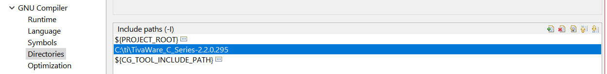
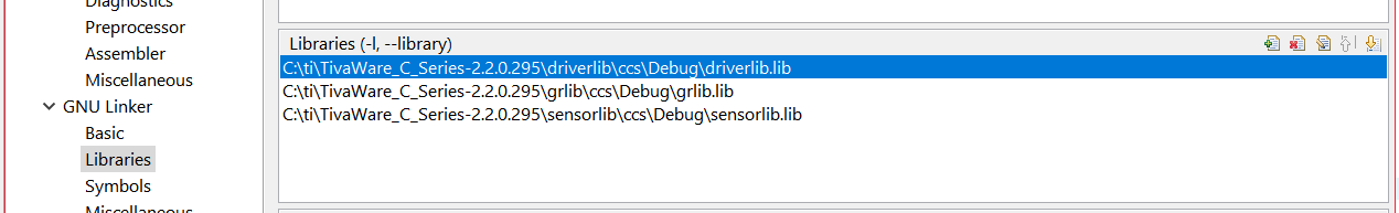
- add the three library files (DriverLib, SensorLib, GrLib) in GNU Linker
- Modify the startup file (tm4c123gh6pm_startup_ccs_gcc.c) to include all four interrupt handlers: GPIO B Interrupt handler, systick handler, I2C2 handler, and Touch Interrupt handler (which uses ADC3 interrupt).
TO DISPLAY AN IMAGE ON LCDThere are some steps to be followed to display any image on LCD Display. We can use the pnmtoc executable provided with the Tivaware folder to convert any image from pnm format to a .c file containing the image data in a constant array. (In the location, Tivaware_C_series-2.2.0.295 -> tools-> bin-> pnmtoc.exe.). So first, we need to scale the image, get the image indexed, and export it as a pnm file.
Steps to be followed:
-
Download and Install GIMP 2.0 (GNU Image Manipulation Program) on your computer.
-
Open GIMP and go to ‘file->open’ and select the image to display.
-
Go to ‘image->scale image’. Scale the image accordingly so that it fits in the display (which is 320×240).
-
Go to ‘image->color->indexed’. Make it to indexed mode (from default RGB), choose 16 / 255 color palette on the next screen, and click apply.
-
Now export the image as a pnm file by ‘file->export as-> pnm image’.
(NOTE: you will get the ‘select the export format’ option in the bottom left corner of the export screen, there, choose pnm format.)
-
Keep both xyz.pnm file and pnmtoc.exe file in the same folder and open the command prompt from that folder.
-
In cmd, type ‘pnmtoc -c xyz.pnm > xyz.c’. This will create the .c file, which contains the image and palette data. NOTE: while entering the above command, ensure the current working directory is the same as the one you kept (xyz.pnm and pnmtoc.exe) files.
-
Now you can copy the image data from the .c file created and use it in your code by changing the name of the constant array and using the ‘GrImageDraw’ function.
CREATING MAZES
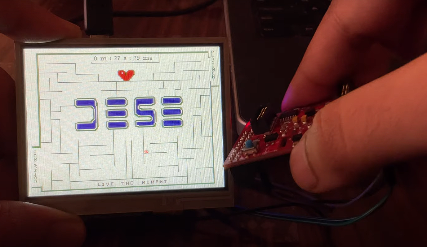
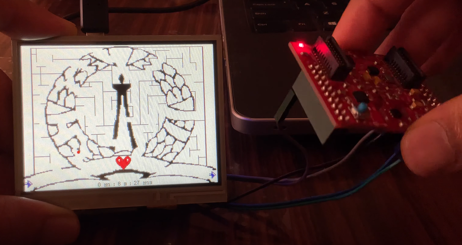
For this project, we created two mazes, DESE and IISc_logo. The mazes are created using pixelart.com. This website allows us to choose the canvas size as 320×240 and draw at a pixel level. This also supports features like mirror-XY layers. Draw the maze as you like in the 320×240 canvas and download it as a .png file.
After downloading the image, also make a b&w copy of the same image (using an online editor). We use this b&w image to restrict the ball movement at the maze walls.
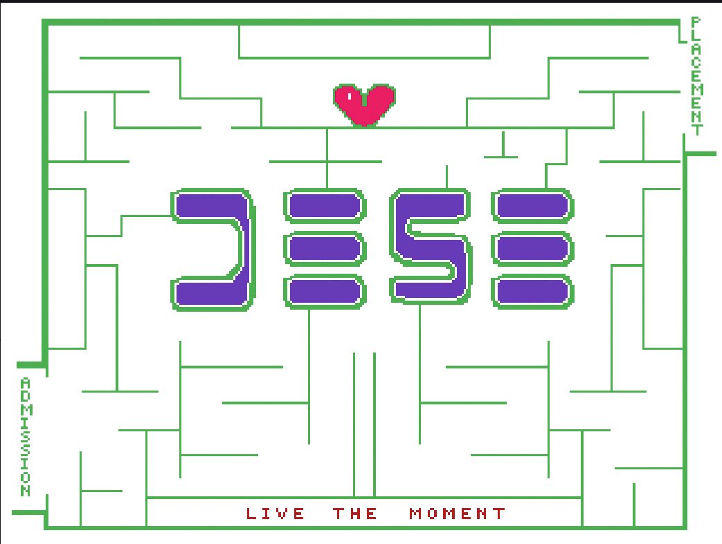
Figure 1.1 DESE Maze Layout
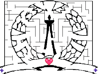
Figure 1.2 IISc Maze Layout
CORE FUNCTIONALITY OF THE CODE
The ball used in the Game (see demo) is a red circle of radius 2 (drawn using GrCircleFill). The ball starts at a preset starting location. The player has to navigate through the maze to the end. A while loop will continuously get the accelerometer values (in X, Y axes) and modifies the new ball location accordingly. Here, suppose the new accelerometer value is in the positive X direction. In that case, the new center coordinates of the red circle(ball) will be updated to 3 pixels right, and the old circle is redrawn with background color (effectively erasing the ball), and the new red circle is drawn with new ball coordinates. However, we also have to check if the ball is touching the maze walls while doing so. If it touches the maze walls, then the corresponding movement has to be restricted. Note that we also have to check if the ball pixels are in contact with the maze (not only the center pixel coordinates).
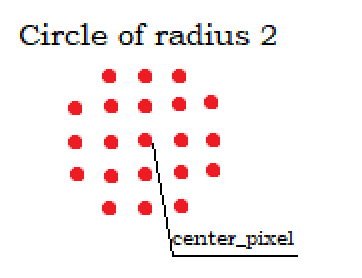
Figure1.3 This is how a ball of radius 2 is printed
To check the location of walls, we are also storing the maze in binary format (0,1) where there is a black pixel; there is a ‘1’ in the stored image. So, when the ball moves from the old location to the new location (3 pixels away), the program will check for possible touches with the maze during its movement.
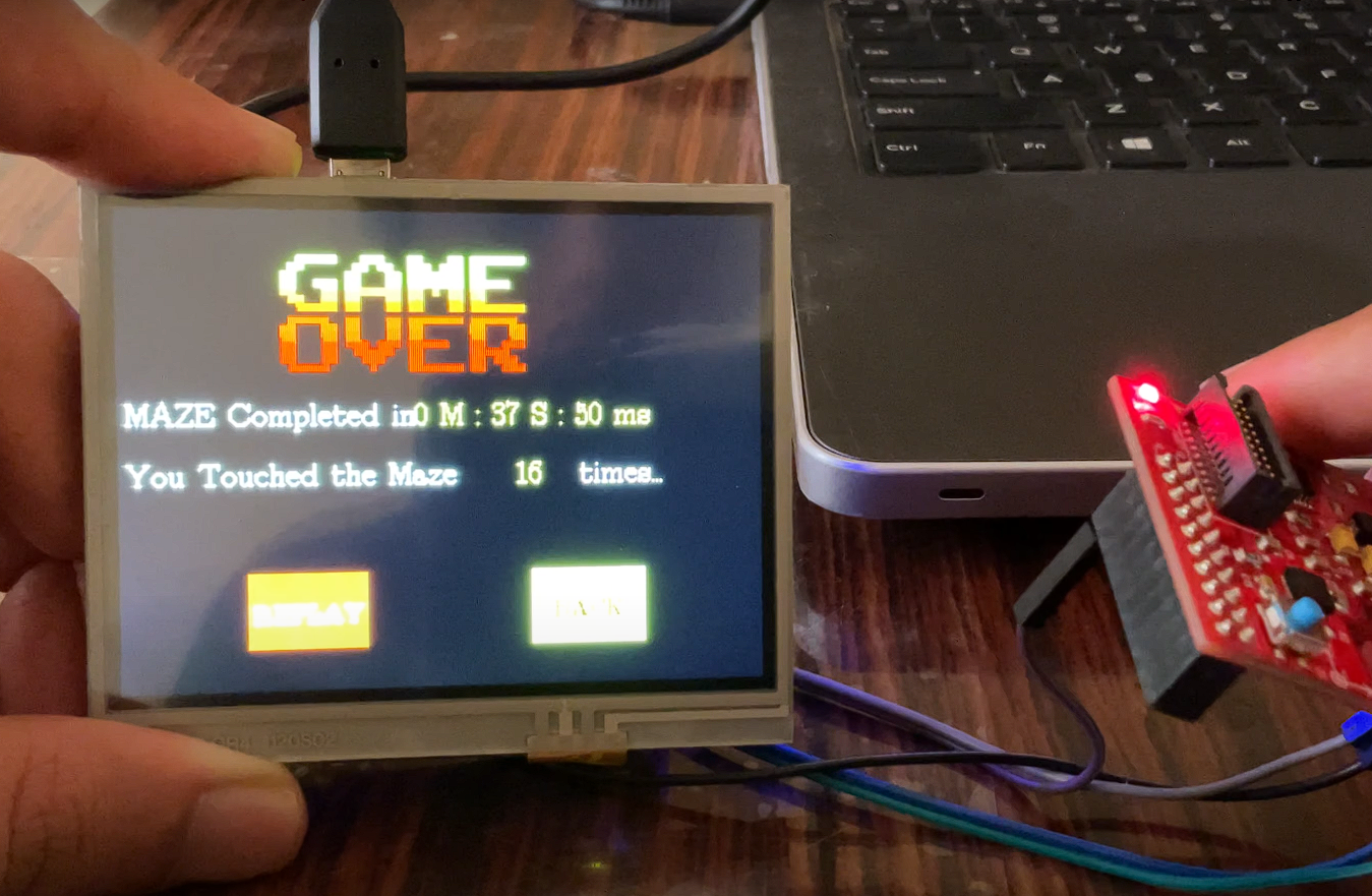
When the ball finally reaches the finished space of the maze, the Game Over screen will flash, asking the player whether he wants to replay the same level or if he wants to go back to the main menu. The Game over screen also shows the time taken by the player to complete the maze and the number of times he touched the maze (lesser is better).
STORING THE MAZE BLUEPRINT
We need to store the image data as 0s and 1s to restrict the ball movement at the maze walls. First, the maze image has to be converted to black and white and, using the ‘imbinarize’ function in MATLAB, store it as a 240×320 characters matrix. Then write the script, which will generate a 2-D array of uint8_t integers with maze data. Therefore, since each uint8_t can store 8 bits, we get a 40×240 array. The MATLAB code for the above functionality can also be found in the project folder/MATLAB functions. So, using this array, we can check this array for each ball movement to see if the ball is in contact with maze walls.
SYSTICK TIMER
We use a systick timer in our project to trace the time taken by the user to complete the maze. Since the clock used for the project is 40MHz, we must choose the reload value accordingly to get a systick to interrupt every 10ms. Here, for 10ms, we need a reload value of 400000 to get an interrupt at every 10ms. (1/40000000) *400000 = 0.01.
So, using a systick timer, we can keep track of time and continuously print the same on the display while the Game is on.
FUTURE WORK
The Maze game can be improved by
- Adding more levels with colorful maze backgrounds.
- Dynamically controlling the speed of the ball according to the tilt.
- Adding user options to change the ball color and ball speed.
- Creating a ‘Score’ based on the time taken and the number of touches with maze walls and storing high scores for each level in flash memory, so that data can be stored even when the device is turned off.
PROJECT CODE
https://github.com/Suraj-Das-K/MazeGame
PROJECT DEMO
https://www.youtube.com/watch?v=yiMThEu9ZJk
PROJECT TEAMMATES
Suraj Das K
Sharath Lohith Tirumala
Jatothu Suman
-
Recent Comments