
Line-Follower Robot Implementation
Introduction and Problem Statement:
A Line-Follower Robot is a machine capable of navigating through a line drawn on a
background. The colors of line and the background should be sufficiently in contrast to
each other for this to work, since the robot differentiates between them using InfraRed
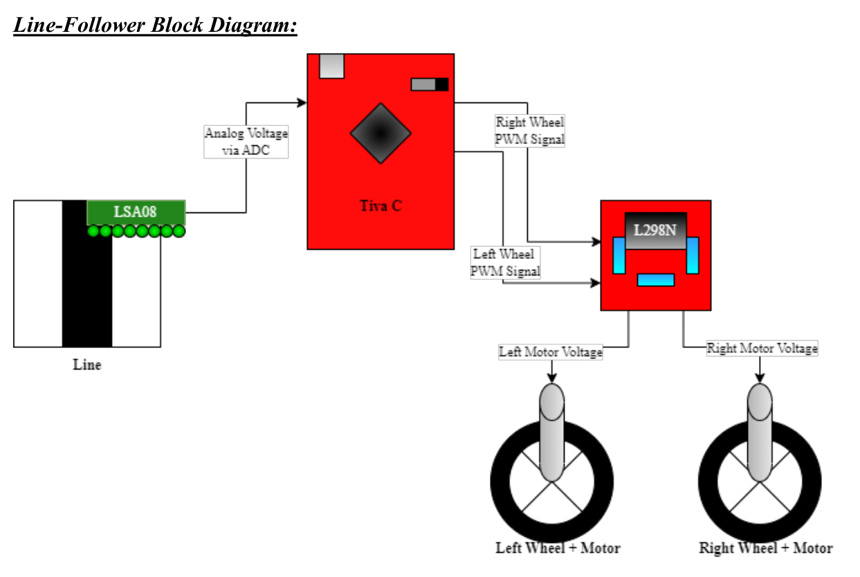
sensors. The data form IR sensor then goes to the microcontroller (TIVA C in our case),
which controls the rotation speeds of the wheels according to a control algorithm
implemented.
A safe to use Fully Autonomous Self-Driving Vehicle should at least be capable of:
1) Navigating through a provided path,
2) Detect moving objects around itself,
3) Detect stationary obstacles in its way,
and control its speed and direction as needed.
A Line-Follower Robot implements the path navigation property, and is thus a precursor
to a Self-Driving Vehicle. In this project, we implement the functionality to follow a dark
line against a light background.
Components Used:
1) Tiva C series Launchpad with TM4C123GH6PM microcontroller (cortex M4-
architecture)
2) Cytron LSA08 Infrared Sensor Array
3) Two geared DC motors (12V and 300 rpm)
4) L298N H bridge motor driver
5) LiPo battery (11.1V, 2200 mAh)
6) Two Wheels (8 cm diameter) + One small dummy wheel to provide balance
Component Details:
Tiva C TM4C123GH6PM microcontroller launchpad provides us with the following
peripherals:
1) ADC (Analog to Digital Converter) – Needed to process analog input from LSA08
(IR Sensor Array used)
2) PWM (Pulse Width Modulation) – Needed to provide individual voltage supplies to
the wheels for speed and direction control
3) General Purpose Timer – Needed to provide accurate periodic interrupts to process
data at a deterministic rate
It consists of Cortex M3/M4 processor having the following features:
• Harvard architecture with unified but fixed memory layout
• 32-bit embedded processor
• Greater performance efficiency
• More work with less latency
• Low power & Low cost < $1
• Enhanced determinism• Nested Vectored Interrupt Controller to service interrupt in known number of cycles
• Improved code density
• Only supports Thumb 2 instruction set
• Ease of use
Cytron LSA08 Infrared Sensor Array module has eight infrared sensors, and can be
calibrated to detect light line on a dark background OR a dark line on a light background.
Depending on the position of the line with respect to the sensors, the module generates an
output voltage between 0 to 4 V, with the junction detection voltage being 4 V.
If the line is detected at the exact centre of the sensor array, the generated voltage is 1.9 V,
which we use as a reference for our control system transfer function.
L298N Motor Driver is a dual H-Bridge motor driver which allows speed and direction
control of two DC motors at the same time.The module can drive DC motors tha have
voltages between 5 and 35V, with a peak current up to 2A.
Mechanical Structure:
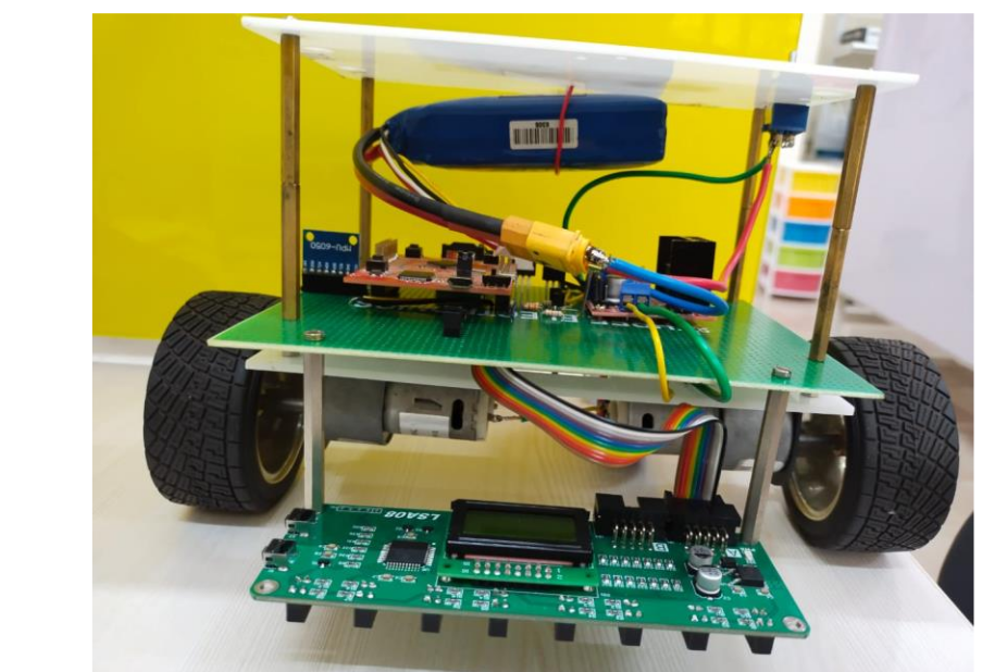
L298N and Tiva C are mounted on 1st tier just above the wheels. 2nd tier contains the LiPo
battery and a switch to route power. LSA08 is below the 1st tier and in front of the rest of
the structure to allow some processing time for outgoing signals from LSA08 to Tiva C.
Back wheel is a dummy wheel to prevent the structure from toppling due to pseudo-force
caused by the forward motion, all without hindering the robot’s motion. Side wheel
motors are controlled by L298N according to PWM signals from Tiva C.
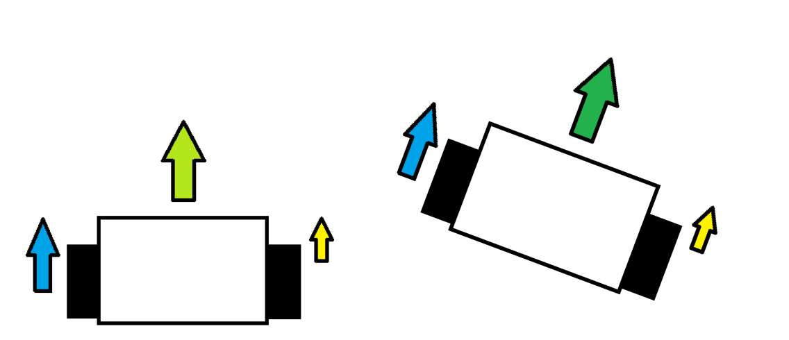
Working Principle:
The direction of motion of the bot is determined by the relative speeds of the left and
right wheels, e.g., if left speed > right speed, left wheel covers more distance than the
right wheel in the same time, thus pushing the overall bot velocity vector towards the
right, and vice versa.
It is intuitive that the ideal case would be when the line is always at the mid-point of the
IR sensor array. However, this is possible only if the path is one straight line from start to
finish. To follow the line, the bot should sense the position of the line with respect to the
IR sensor array’s mid-point, and should infer the difference between them as the position
error. This value of position error should then be used by the bot to move itself such that
the error decreases upon the next check. This can be achieved by altering the left and right
wheel speeds appropriately, such that the bot moves in the desired direction, trying to
position itself such that the line is placed at the mid-point of IR sensor array, i.e., zero
error.
Thus, we need to implement a control system transfer function between the position error
(input) and corresponding wheel speeds (output).
The goal is to adjust the wheel speeds such that the resultant direction of motion results in
a lower position error.
Implementation and Testing:
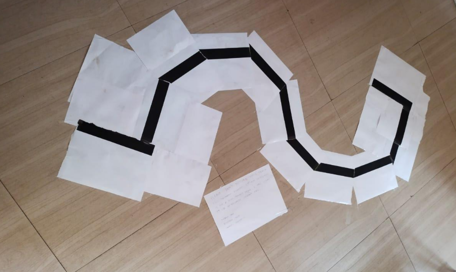
The above track was used to test the implementation of the described control system
transfer function. The shape made sure turns in both directions and varying sharpness are
being made properly, without leaving the line. It is to be noted that speeds of individual
wheels are directly proportional to the duty cycle applied to the respective PWM ports.
Since we have an additional wheel for support and it doesn’t exactly align with the centre
of mass of the bot, it is upon the left wheel to drag a little more weight. We handle this by
adding some offset to the left wheel duty cycle. This offset is another hyperparameter,
closed in on by hit and trial.
We started by applying a simple Proportional Controller, which took in (Vin – Vref) as the
error. Vin = Analog input from LSA08; Vref = 1.9 Volts = Vin | line at middle of sensor array.
Primary problem we faced with this implementation was of overshoots, i.e., the bot had a
tendency to run at a fast speed and ignore sharp turns.
To overcome this problem, we switched to a Proportional-Integral Controller, by
introducing a total_error term which served as an accumulator for all the previous error
terms. This resulted in dampening of the speed, and consequently the bot started getting
more time to process the sensor input, and thus the line-following aspect improved a lot,
at the expense of speed.
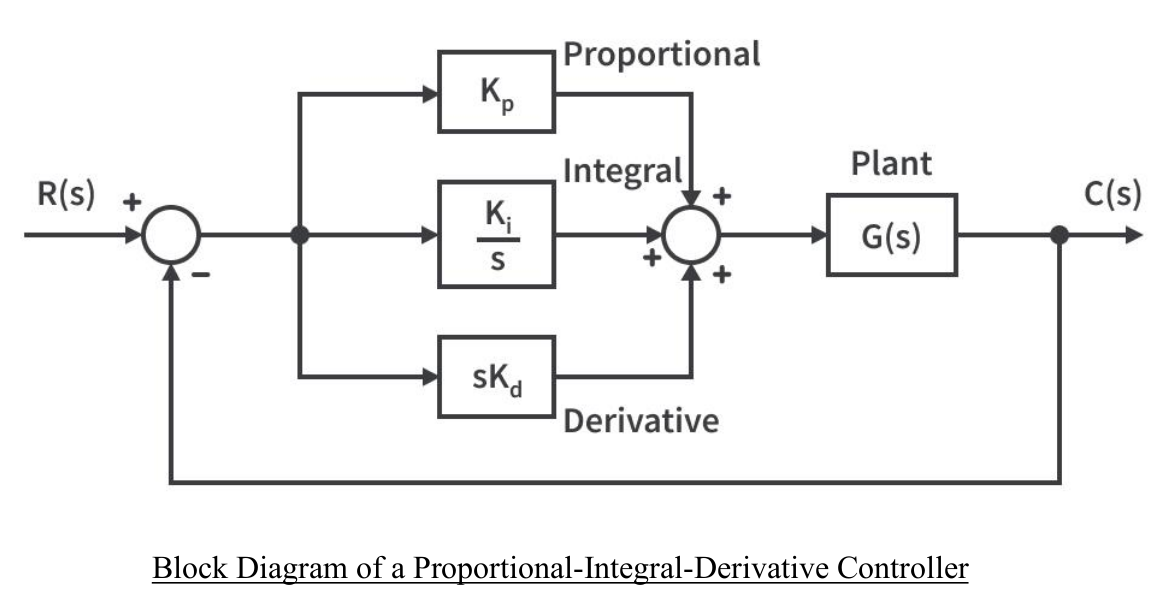
After parameter tuning, we settled on controller coefficients Kp = 0.13, Ki = 0.00026, and
Kd = 0.
We didn’t apply Differential Control since we’re not very concerned with the transient
response in this case; steady state response matters much more.
Test Cases, Results and Inferences:
The final bot was subjected to various test cases and from the respective performances,
some inferences can be drawn regarding the hyperparameter limits:
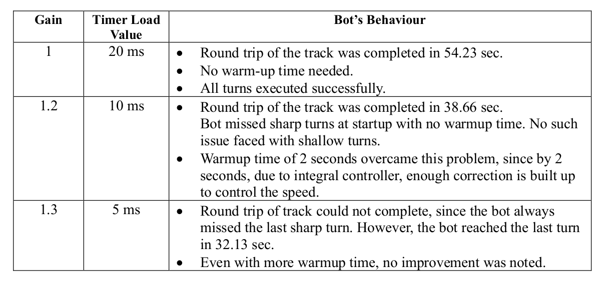
The above table suggests that gain of 1.2 improves the speed of the bot significantly.
However, a warmup time of a few seconds is needed to avoid the startup runawayproblem.
In a safety-first scenario, the conservative values of Case 1 are the best fit. However, Case
2 is better equipped for, say a car race. To achieve even higher speeds like Case 3, the
controller coefficients need to be tweaked further.
To improve the average speed, a hybrid algorithm can be applied to switch between cases
depending on the correction value calculated.
E.g., if the correction factor generated is very small, it would suggest that the line is more
or less straight, and thus, maybe Case 3 can be employed. As soon as a bigger correction
value is generated, suggesting a turn, Case 1 or 2, depending on the value, can replace as
the operating values. Please note that this is a hypothesis and not tested.
code:
Demo: Line Follower Self Balancing Bot
Recent Comments