
Problem Statement
To display files (raw images , text files , folders and their contents) stored in SD Card on the Nokia LCD.
Resources
- TIVA microcontroller (TM4C123g).
- NOKIA LCD Display.
- SD Card formatted in FAT 16.
- Eclipse IDE.
- gcc.
Project Overview
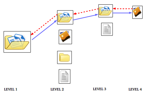
The project showcases how to read the contents from a SD card (FAT 16 formatted) and display it on the LCD screen. The SD card contents include raw image files(.h format), text files , folders with one or more files .This can handle recursive sub-folders too.On reset , the contents of the SD card are displayed .This may include files and folders.If a file is selected,its contents are displayed . If a folder is selected , its contents that may include files or folders are displayed . This folder selection is allowed recursively and the folder path is retraced back in the same manner.
Demo
The demo links are uploaded in the YouTube channel. The links are given below. A main link is provided with complete demo showing all the functionalities. There are three other links that show the sub parts of demo. The title contains the part of the demo being demonstrated.
Interface Sd card with LCD (main full demo) : https://youtu.be/IRLs9MHSHL8
Interface Sd card with LCD – Image file in sub folder : https://youtu.be/ntbkmy8ares
Interface Sd card with LCD -Image file in main folder(main full demo) : https://youtu.be/l5Qg7YpSkEQ
Interface Sd card with LCD – Recursive folders(main full demo) : https://youtu.be/yAEoAsxo3-I
Serial Peripheral Interface
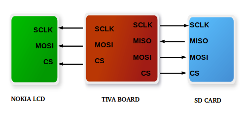
Serial Peripheral Interface (SPI) is an interface bus commonly used to send data between micro controllers and other peripherals such as sensors,display units and SD cards. It uses master-slave architecture where the data communication is synchronized to the clock given as reference by master to slave(s). The master can select its slave using Chip Select (CS). It uses separate data lines, for the 2-way communication.The master may send data to the slave (MOSI – Master Out Slave In) or may read data from the slave (MISO – Master In Slave Out). Hence, it can be used as a 4-wire communication with dedicated lines for Chip Select (CS) , Clock (SCS), MOSI and MISO.
Most of the micro-controllers have Hardware Peripheral support for 8-bit SPI. So, to accommodate 9-bit SPI, a technique called Bit-Banging is used where a GPIO pin is set and sampled in software instead of hardware.In our project, both SD Card and the LCD display supports SPI but with different data width and slight change in functionality.
SD Card
- 8-bit SPI communication : Hardware peripheral can be used.
- Signals for Communication : CLK (clock), CS (Chip select), DI (data in – MOSI), DO (data out – MISO).
Nokia LCD
- 9-bit SPI communication : Bit-Banging can be used, if there is no hardware support.
- Signals for Communication : CLK (clock), CS (Chip select), MOSI (master out, slave in).
Understanding FAT 16 File System
FAT system is the widely adapted file system for SD cards. Depending on the SD card size, appropriate FAT system has to chosen. In, our case we have used (<= 2GB) SD Card, hence we have chosen FAT-16 file system. The SD card has to be formatted correctly in FAT 16 otherwise the contents of the card will not be read properly.
Certain commands can be run on the UBUNTU terminal to have a look at the Master Boot Record . This will help us to understand the concepts of the file system and also lets us to verify whether the FAT parameters calculated such as root table entries , bytes per sector , sectors per cluster , reserved sectors , fat copies etc are proper or not . The list of commands followed by an example to interpret them correctly is given below :
- sudo fdisk -l : This will give the partition table of the system (mostly in /dev/sda) . The SD card’s file system(FAT 16 / FAT 32 / NTFS) , size , Id will also be given if the card is in proper format.This can be in /dev/sdb where /sdb varies from one system to another.
- sudo hexdump -s0x00 -n512 -C /dev/sdb : Assuming SD card at /dev/sdb , running this command will give 512 bytes of data located at address 0x00 of the /dev/sdb . At the offset of 8 bytes from 0x1be , you can get the partition sector entry where the SD card lies.This is the sector number(say x).Multiply it by 512 (This file system has 512 bytes per sector) to get the location where the card contents lies (y = x * 512).
- sudo hexdump -s0x00 -n512 -C /dev/sdb1 or sudo hexdump -s0x0y -n512 -C /dev/sdb : This will take you to the location of the SD card. From here onwards all addresses are with respect to sdb1.
The table that follows will provide essential FAT parameters at the locations as listed below :
0x000B (2 bytes) : Number of bytes per sector(usually 512).
0x000D (1 byte) : Number of sectors per cluster.
0x000E (1 byte) : Number of reserved sectors.
0x0010 (1 byte) : Number of fat copies (usually 2).
0x0011 (2 bytes) : Number of root entries.
0x0016 (2 bytes) : Number of sectors per FAT.
FAT1_address = Number of reserved sectors * Number of bytes per sector.
FAT2_address = FAT1_address + Number of sectors per FAT * Number of bytes per sector.
Root_directory_address = FAT2_address + Number of sectors per FAT * Number of bytes per sector.
Data_region_address = Number of root entries * 32 + Root_directory_address.
(Note LITTLE ENDIAN format is followed throughout)
File or Folder details
The Root entry table contains the information of all files and folders in the home directory. This has 64 pages and each page can have 16 entries. Each entry is of 32 bytes. Assume the address of an entry is z. Then the file details can be extracted as follows :
- File name : 8 bytes at (z) – file name is always stored in Uppercase
- File extension : 3 bytes at (z + 0x08) – file extension is always stored in Uppercase
- Cluster number : 2 bytes at (z + 0x1A)
- File size : 4 bytes at (z + 0x1C)
- File address : Data_region_address + (Number of bytes per sector) * (No of sectors per cluster) * (Cluster Number – 2)
If the entry is a folder, it does not have an extension and its size is 0. The contents of the folder is present as another table at the address that can be calculated similar to file address. The details of the folder contents can be evaluated from the table as above.
Example
The following figure are the snapshots of the entries of a SD Card with FAT 16 format .The calculations following will help calculate address of the root table and the data entry region. Also the example demonstrates how to find file_address and file_size for a particular file.
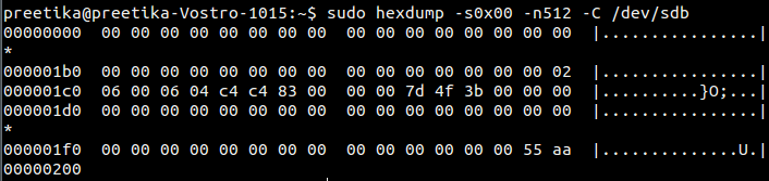
Partition sector entry : 0x00000083
Address of Partition sector entry : 0x10600
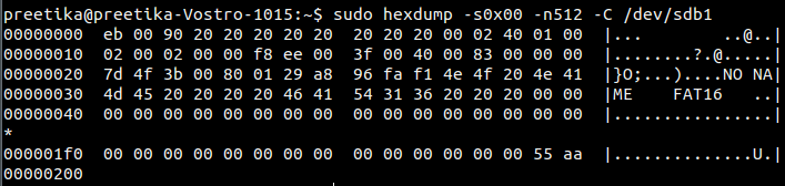
Number of bytes per sector : 0x0200
Number of sectors per cluster : 0x40
Number of reserved sectors : 0x01
Number of fat copies : 0x02
Number of root entries : 0x0200
Number of sectors per FAT : 0x00EE
FAT1_address : 0x200
FAT2_address : 0x1DEE
Root_directory_address :0x3BA00
Data_region_address : 0x3FA00
![]()
File name : COLOURS
File extension : TXT
File : COLOURS.TXT
File cluster number : 0x0014
File address : 0xCFA00
File size : 0x000000D0
Nokia LCD Interface
Nokia LCD 6100 is used in our project. The diplay consists of 132 x 132 pixels, 12-bit color rendition (4 bits red, 4-bits green, 4-bits blue) and works at 3.3 volts. The Nokia LCD here uses a two-wire serial SPI interface (clock and data). The master (micro-controller) generates the clock and data signals to communicate with the slave (LCD).The display used here is write-only(MISO = disabled , MOSI = enabled). Here 9 bits are transmitted to the display unit serially (Bit Banging). The ninth bit indicates whether a command (logic high) is sent or data (logic low). Chip Select has to be made low at the beginning of each transfer . The data or command gets latched at falling clock edge i.e. 1 to 0 transition.
Implementation
Firstly,interface the SD card and LCD with the micro controller(Tiva).The SD card communicates with the Tiva board using SPI via PORT A. It has dedicated GPIO pins for Chip Select (PA3) , MOSI (PA5) , MISO (PA4) and CLock (PA2). Here we are just reading the SD card contents and are not writing into it.The LCD unit is also interfaced to the board via PORT C. The communication happens through SPI. Only writing to the LCD is permitted and not reading from it. Dedicated GPIO pins Chip Select (PC5), MOSI (PC7) and Clock(PC6) are allocated for communication.
Once interfaced , the FAT parameters are calculated as explained above. Then the file list of home directory is obtained from the SD card. This includes the text , image files and also the folders present. This is displayed on the LCD screen. Once the list is displayed , the user can select the file or folder . If some file is selected(image or text), its contents are displayed.If a folder is selected,the file list of that folder is displayed.The user can further navigate and choose the file or folder present in the sub directory.The contents are displayed accordingly.
User Interface
PORT D and PORT F are used to help user to navigate through the LCD screen.Two switch buttons from PORT D (PD1 and PD2) help to scroll up or down the file or folder menu . The switch buttons from PORT F (PF0 and PF4) are used to view the file contents and returning back to the previous menu. Also they help to enter a folder and return from it.
Future Scope
Modification of display interface (Scroll text up and down , zoom in and out of image). Integration of Joystick would help. These options can also be explored by using a touch sensitive LCD.
References
- SPI with SD Card – http://elm-chan.org/docs/mmc/mmc_e.html
- FAT16 system – https://www.win.tue.nl/~aeb/linux/fs/fat/fat-1.html
Team Members
Preetika Tandon
Radhika N
Recent Comments