
The Global Positioning System (GPS) is a space-based satellite navigation system that provides location and time information in all weather, anywhere on or near the Earth, where there is an unobstructed line of sight to four or more GPS satellites. It is maintained by the United States government and is freely accessible to anyone with a GPS receiver. The GPS program provides critical capabilities to military, civil and commercial users around the world. In addition, GPS is the backbone for modernizing the global air traffic system.
A GPS receiver calculates its position by precisely timing the signals sent by GPS satellites high above the Earth. Each satellite continually transmits messages that include
- the time the message was transmitted
- satellite position at time of message transmission
The receiver uses the messages it receives to determine the transit time of each message and computes the distance to each satellite. These distances along with the satellites’ locations are used with the possible aid of trilateration, depending on which algorithm is used, to compute the position of the receiver. This position can be displayed as latitude and longitude.
STM32L Discovery Board Details
STM32L basic board
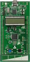
The STM32L Discovery board is based on an STM32L152RBT6 and includes on-board ST-Link/V2 debug interface. As can be seen from the picture, most of the General Purpose I/Os (GPIOs) are brought out for use towards the sides of the board.
The main features of the board which were used in this project are:
- The external 5V & GND supply pins which can be used to power USART add-on boards
- The GPIO ports brought out to sides of the board
- Built-in USART module
The programming of this board can be done on the open-source toolchain as described in the article – STM32L-DISCOVERY (1), or on the evaluation version of Keil uVision platform.
GPS Receiver
GPS constellation in motion with the Earth rotating
The space segment (SS) is composed of the orbiting GPS satellites, or Space Vehicles (SV) in GPS parlance.The orbits are centered on the Earth, not rotating with the Earth, but instead fixed with respect to the distant stars.The orbits are arranged so that at least six satellites are always within line of sight from almost everywhere on Earth’s surface.The result of this objective is that the four satellites are not evenly spaced (90 degrees) apart within each orbit.About nine satellites are visible from any point on the ground at any one time (see animation at right), ensuring considerable redundancy over the minimum four satellites needed for a position.
The GPS Receiver uses NMEA protocol.
NMEA is a standard protocol, use by GPS receivers to transmit data. NMEA output is EIA-422A but for most purposes you can consider it RS-232 compatible.It uses 9600 bps, 8 data bits, no parity and one stop bit. Each sentence begins with a dollarsign ($) and ends with a carriage return linefeed (<CR><LF>).
Eg.
$GPGSA,A,1,,,,,,,,,,,,,,,*1E
$GPGSV,3,1,10,02,68,308,,04,48,018,,10,47,101,,27,43,258,*73
$GPGSV,3,2,10,09,39,276,,05,34,177,,28,32,120,,12,23,331,*71
$GPGSV,3,3,10,17,18,056,,26,07,192,*7D
Analog Add-On board
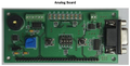
Analog Add-On Board
The Analog add-on board has the following features:
- Temperature Sensor
- Buzzer
- LED array
- DIP switches
- USART
- Anti-Tamper and Wakeup unit
USART is used to interface STM32L Discovery Board with RS232 Levels.
The schematic of the add-on board can be found here :Analog_Schematic (2)
Hardware Interconnections
[[File:|250px|thumb|right|Interconnection]] The GPS Receiver module provides RS232 data. This is given to STM32L Discovery Board using Analog Add-On Board. The GPS Receiver module is powered by external 12V DC Adapter.
The following are the connections to be made between the STM32 Board and the Add-On Boards:
RS232 cable(twisted) between GPS Receiver module & Analog Add-On Board.
STM32 Board : STM
Analog Board: An
| Sr.No. | Source | Destination | Remarks |
| 1. | STM.EXT_5V | An.J.1 | 5V Supply to Analog Add-On Board |
| 2. | STM.GND | An.J.2 | GND to Analog Add-On Board |
| 3. | STM.PB6 | An.J.27 | USART1TX of STM32 to TX of Analog Add-On Board |
| 4. | STM.PB7 | An.J.30 | USART1RX of STM32 to RX of Analog Add-On Board |
Format of received data stream
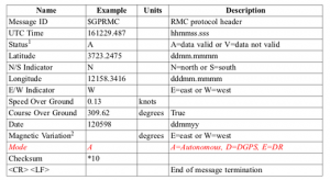
RMC—Recommended Minimum Specific GNSS Data
Table contains the values for the following example: $GPRMC,161229.487,A,3723.2475,N,12158.3416,W,0.13,309.62,120598, ,*10
Basic Algorithm
1. After initialisation, the system waits for user button to be pressed. The corresponding message is displayed on the LCD.
2. When user button is pressed, USART RX is enabled. It will receive first 750 bytes to get enough information required to locate correct
  position. Now the receiver will be disabled.
3. Received stream of lines is scanned for starting word $GPRMC.
4. If match is found then the same line is further checked for valid/invalid data. If receiver was able to collect information from 4 or
  more than 4 satellites then only the preceding data is valid. This is indicated by A/V(A-valid,V-invalid).
5. If data is invalid then it will go back to point 3.
6. If data is valid then preceding bytes will be containing latitude and longitude. These are extracted and displayed on LCD.
7. If in the entire stream data was invalid than corresponding message is displayed on LCD.
8. The system waits for user button to be pressed.
Project Team
- Akanksha Chaturvedi
- Sumana T
Recent Comments