
What we need to do?
A Pulse Oximeter sensor can be used to measure various physiological parameters such as heart rate, Oxygen saturation and Hemoglobin content. This project is aimed at reliably measuring the Heart Rate of an individual.
What are our requirements?
As part of a daily exercise routine or during medical examinations, measurement of the Heart Rate (HR, hereafter) is a crucial step to evaluate the fitness of the heart. Making the measurement setup compact is also important, since this feature can make the lives of medical examiners and patients a bit easier and also ensure portability. Being a crucial physiological parameter, HR measurement must also be accurate.
Hardware requirements?
The sensor
- Since the measurement will be of HR, which is a physiological parameter,the sensor to be chosen must be non-invasive, reliable and compact. Therefore, a Pulse Oximeter sensor was chosen. For our project, the Pulse Oximeter procured was NONIN DC1050.
The Analog Front End
- An Analog Front End was designed to convert the sensor output into a form that can be processed by the microcontroller.
The microcontroller
- Tiva C Series TM4C123G was chosen for our project.
More Details?
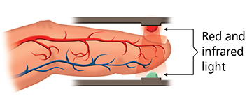
Fig.1 Pulse Oximeter with two LEDs (Courtsey : www.nonin.com)
1.Pulse Oximeter
A Pulse Oximeter sensor works on the basis of light absorption. This sensor consists of single or multiple LEDs and a Photodiode,in an enclosed arrangement as shown in Fig.1. The wavelengths of the LEDs are chosen according to the absorption spectra of different blood components to be measured (usu. 660nm and 940nm for two LED sensor). The blood components absorbs different wavelengths differently. Another factor deciding the absorption is the concentration of the blood components. The non-absorbed light is incident on the Photodiode and gets converted into photo-current. This current is the output of the Pulse Oximeter sensor.
2.Analog Front End
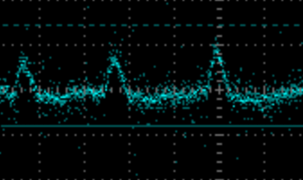
Fig.2 PPG Waveform
The Pulse Oximeter sensor generally produces a very low current output, which must be converted to a high enough voltage for the Microcontroller to process. This is done using a Trans-impedance Amplifier. Also, the sensor output will contain Power Supply noise and High frequency noise. These noise components must be filtered off using a notch-filter and a Low Pass filter respectively. The analog signal usable for further processing by the microcontroller, also called the PhotoPlethysmoGram (PPG), is shown in Fig.2.
3.Processing
The PPG signal must now be sampled, stored and processed. The PPG signal is usually having a frequency of 1.2-2 Hz. For sampling this signal, the ADC of the microcontroller was configured to sample at a frequency of 1kHz. To store these samples, a Buffer of size 2048 was used which can hold the samples of two cycles of the signal. For calculating HR, the peaks of the signal and the time gap between these peaks must be identified. To get these, a window of samples were selected, out of which, the maximum, minimum, their indices and slope was identified. The window is traversed through the buffer. Whenever there is a change in slope, depending on the change, either a peak or a trough has occured. From this, the HR was calculated.
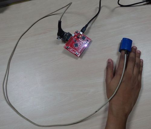
Measurement Setup
- As seen in the image, a Pulse Oximeter sensor is connected to the Analog Front end.
- The Analog Front end output is provided to the microcontroller.
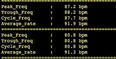
Results
- The results were displayed on the terminal using UART.
- Peak_Freq indicates the heart rate calculated from the peaks identified in the buffer.
- Trough_Freq indicates the heart rate calculated from the troughs identified in the buffer.
- Cycle_Freq indicates the average value of the heart rate calculated on a single cycle i.e. on a single set of values from the buffer.
- Average_rate indicates the average value of the heart rate calculated over the past 16 cycles.
Issues Faced
For a sampling rate of 1kHz, a DMA is not actually required for transferring ADC FIFO contents.
Still, we had tried to use the DMA as a part of extending the mini project. The ADC-DMA interaction was not working as expected.
Future Work?
The Project will be extended to measure the Oxygen saturation(SpO2) and Total Hemoglobin(tHb).
For this, the Pulse Oximeter sensor must be implemented using three LEDs with different wavelengths and an LED driver.
Recent Comments