
1. Build a General Purpose Timer Project
Use GPTM block 0 Timer A (Timer0A) as a 16-bit count-down counter to periodically generate a timeout interrupt to turn on three LEDs, PF3∼PF1, via GPIO Port F. The input clock to the timer is the 16 MHz system clock, and the period to be counted in the Timer0A counter is 65.536 ms.
To perform this periodic interrupt for each 65.536 ms, one needs to:
- Enable and clock the Timer0A for GPTM Block 0.
- Enable and clock the GPIO Port F.
- Disable the Timer0A module before any configuration can be performed.
- Configure the Timer0A to work as a 16-bit count-down periodic counter.
- Load 65535 (65536 – 1) into the GPTMTAILR register as the start value since we want to get the maximum period of time, which is 65.536 ms, for each period.
- Load 15 (16 – 1) into the GPTMTAPR register as a prescale value. After this 16 MHz system clock is divided by this prescaler (16), the working clock for this counter is 1 MHz with a 1-μs period.
- Clear any previous timeout interrupt for Timer0A by writing 1 to an appropriate bit in the GPTMICR register.
- Enable Timer0A timeout interrupt by writing 1 to an appropriate bit in the GPTMIMR register.
- Use NVIC_PRI4_R (Bit 31 – 29 ) to set the interrupt priority level as 3 for the Timer0A.
- Use NVIC_EN0_R (IRQ19) to enable the timeout interrupt for the Timer0A.
- Enable the Timer0A module after these configuration and the Timer0A begins to count.
- Use EnableInterrupts() function to globally enable all interrupts.
- Use an infinitive while() loop to wait for any interrupt coming.
In addition to the main program, one also needs to build the Timer0A interrupt handler:
- Clear the timeout interrupt for Timer0A by writing 1 to an appropriate bit in the GPTMICR register to enable it to be generated in the future.
- Turn on the related LED via GPIO Port F.
2. Use Timer1A and Timer2A timeout events to trigger interrupts
- Configure Timer1A to timeout once every second. In the interrupt handler, toggle the red LED.
- Configure Timer2A to timeout at 10 Hz. In the interrupt handler, toggle the green LED.
3. Measure pulse width using interrupts with a precision of 24 bits and a resolution of 12.5 ns
- The pulse width measurement is performed from rising edge to falling edge.
- The resolution is 12.5 ns, determined by the system bus clock.
- The range is about 25 ns to 209ms with no overflow checking.
Hints:
- The digital-level input signal is connected to two input capture pins, CCP0 and CCP1.
- The bus clock is selected to be 80 MHz so the measurement resolution will be 12.5 ns.
- The rising edge time will be measured by Timer0B without the need of an interrupt and the falling edge interrupts will be handled by Timer0A.
- The pulse width is calculated as the difference in TIMER0_TBR_R – TIMER0_TAR_R latch values.
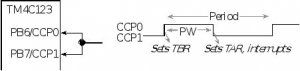
4. Measure the period of a square wave input signal
Hint: To measure the period of a signal we must measure the time between two falling or rising edges.

Figure 10.5: Measuring Period and Pulse Width
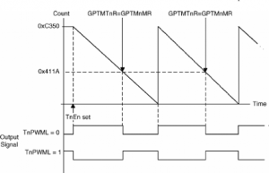
5. Generate PWM
- Generate an output PWM with a 1-ms period and a 66% duty cycle (TAPWML = 0) assuming a 50 MHz input clock. The duty cycle could be 33% if the TAPWML = 1.
- Hint:
- The start value is GPTMTAILR = 0xC350 and the match value in GPTMTAMATCHR is 0x411A.
- Use PLL
- Use Timer A
Recent Comments