
Introduction:
The Objective of the project is to recognize gesture drawn by IMU sensor module and controlling mouse pointer by moving IMU sensor module accordingly.
Motivation:
There are physically disabled person who don’t have hand. They are not able to use mouse device available in the market.Our motivation behind this project is to provide an alternative solution so that they are able to control mouse pointer and use computer with ease.
There are several parts in the project:
- 1. Detect orientation of the IMU device to remove gravitational component.
- 2. A 2D mouse using angular velocity of Gyro sensor.
- 3. Recognize Gesture drawn by IMU device.
- 4. A 3D mouse using accelerometer.
The sensor module we are using has 9 DOF(Degree of Freedom) which means the sensor has 3axis Accelerometer, 3axis Gyro and 3axis Magnetometer.We are using 6DOF our of 9.(3axis Accelerometer and 3axis Gyro)
Working principle of Accelerometer:
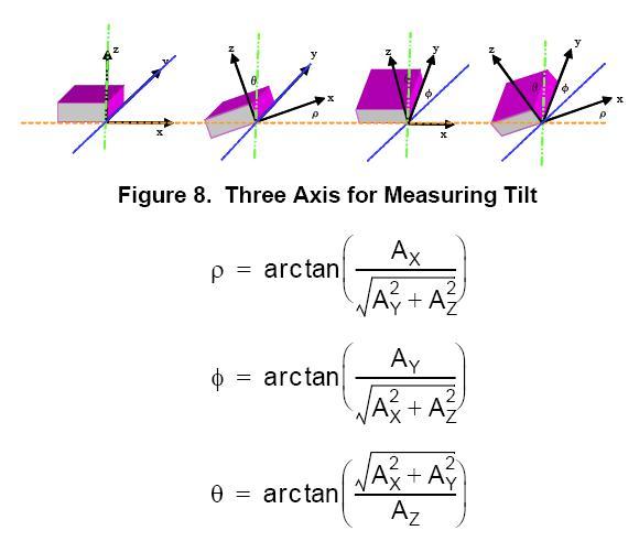
3axis accelerometer provide acceleration experience by the sensor module in each axis.Gravitational force is continuously acting on the sensor.So, acceleration of accelerometer consist of gravitational force and it’s own accelration (called linear acceleration). We have to work on linear acceleration, so we have to subtract gravitational component from each asix. To detect gravity component on each axis we have detected the orientation of the sensor.
How we have detected Orientation of the Sensor:
when the sensor is not moving, the only force acting on the sensor is the gravitational force.So, whenever the sensor is not moving we are calculating orientation with respect to reference axis using following formula.
Ref: http://i1.wp.com/www.geekmomprojects.com/wp-content/uploads/2013/04/accelerometer_angles.jpg
We get angular velocity from gyro for each axis.So, we get angular rotation in each axis using gyro.Whenever the sensor in not moving(which means only gravitational force is acting on the sensor) we set orientation using gravity component on each axis, then onward we are updating orientation by using angular rotation on each axis.
We have used complementary filter to provide efficientn weightage to accemeter data and gyro data for calculating orientation.
Filtered Angle = α × (Gyroscope Angle) + (1 − α) × (Accelerometer Angle)     where
α = τ/(τ + Δt)   and   (Gyroscope Angle) = (Last Measured Filtered Angle) + ω×Δt
Δt = sampling rate, τ = time constant greater than timescale of typical accelerometer noise
Algorithm Flow Chart:
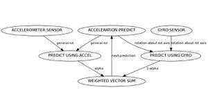
FlowChart
Accelerometer sensor also contains bias which we have detected by keeping axis along gravitational force and calculating difference between 9.81 and sensor reading.
2D mouse using Gyro:
To simulate a mouse pointer using Gyro we are using rotation along x-axis to simulate vertical movement and usng rotation along z-axis to simulate horizontal movement. Once we map gyro angular velocity to correponding pixel movement we have a 2D mouse which works perfectly in real time.
Gesture Recognition using IMU sensor data:
We are using 3axis accelerometer data to detect gesture.So, we have 3 dimensional time series data.We have collected data for 4seconds. Each second has 100 number of samples.In 4 secs we have multidimensional time series data of length 400 and dimenstion 3
We are using K-Means clustering to assign cluster label to test data.
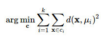
where k is number of cluster.
Here we are classifying between drawing a circle and drawing a rectangle. for distance calculation between centroid and test time series we are using Dynamic Time Warping Dependent mechanism. For our implementation during drawing a particular gesture, 3 axis are corelated to each other that means for a gesture pattern created by each axis is dependent on each other.
When we draw a circle and draw a rectangle it creates different kind of pattern of time series data of x-axis,y-axis and z-axis. Dynamic Time Warping algorithm provides a measure of similarity between two time series data.
Following is snap of pattern:
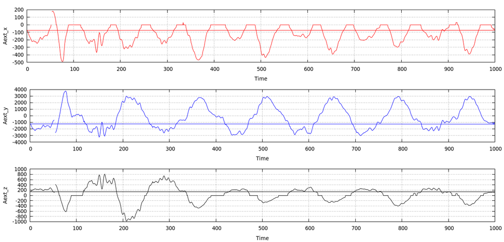
Pattern for Circle
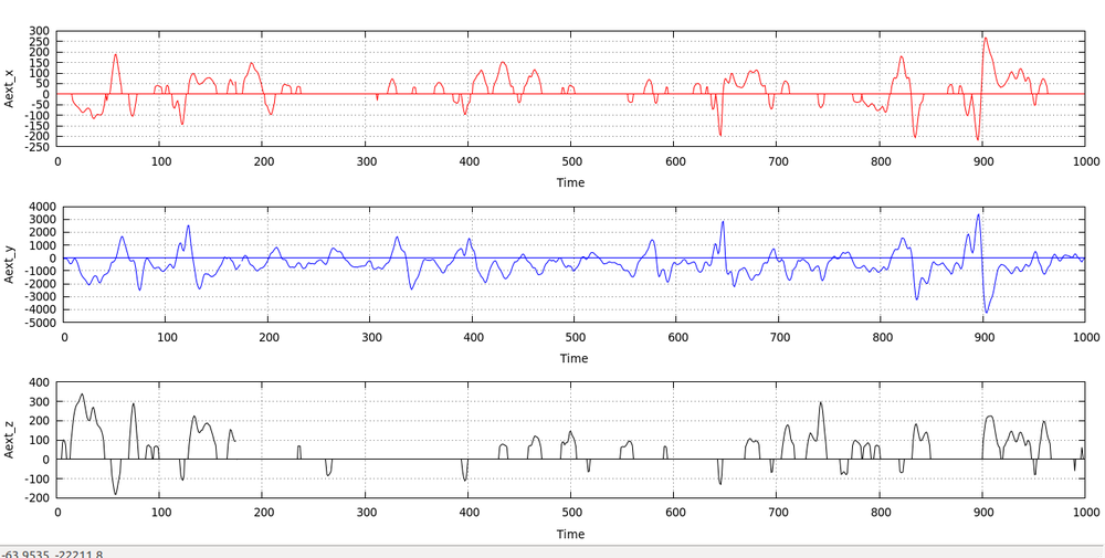
Pattern for Rectangle
3D Mouse using Accelerometer:
Filtering: We have filtered raw accelerometer sensor data using Kalman filter. Detect Orientation: Detect orientation of the device and calculate gravitational force component on each axis.Thus we got linear acceleration. Calculate: Calculated displacement by double integrating linear acceleration data.
	velocity(n)=velocity(n-1)+linearAcceleration×Δt
	displacement(n)=displacement(n-1)+velocity×Δt
Detect direction of movement: We have to detect the sensor is moving towards which direction. X-axis is moving towards right or left.Y-axis is moving towards top or bottom.Z-axis moving towards forward or backward. Calculate pointer Co-ordinate: First we have initialized the pointer to (0,0,0) then depending on the direction of movement we are updating co-ordinate of
pointer using following formula.
If X-axis is moving towards right then
	X_coordinate=X_coordinate+displacementX;
If X-axis is moving towards left then
	X_coordinate=X_coordinate-displacementX;
If Y-axis is moving upward then
	Y_coordinate=Y_coordinate+displacementY;
If Y-axis is moving downward then
	Y_coordinate=Y_coordinate-displacementY;
If Z-axis is moving forward then
	Z_coordinate=Z_coordinate+displacementZ;
If Z-axis is moving backward then
	Z_coordinate=Z_coordinate-displacementZ;
Hardware Component Used:
- Tiva EK-TM4C123GXL by TI
- Sensor BoosterPack
Limitation:
1.We have tried hard to subtract gravitational component from each axis to get linear acceleration efficiently.But it is a very hard problem.If there are 0.01m/s^2 of noise then that will continuously add this noise and as a result the accelerometer will drift. The system we have designed is not 100% accurate to calculate amount of movement by sensor. 2.The microprocessor has a limited amount of physical memory.So, large scale matrix operation for machine learning approach might lead to large amount of delay for processing.
Future Scope:
So far we have classified or recognized 2 gesture, drawing a circle and drawing a rectangle. We can add more number of gestures by properly training our machine.
References:
1. Mohammad Shokoohi-Yekta1,Bing Hu2,Hongxia Jin2,Jun Wang3,Eamonn Keogh1 : Generalizing Dynamic Time Warping to the MultiDimensional Case Requires an Adaptive Approach : http://www.cs.ucr.edu/~eamonn/Multi-Dimensional_DTW_Journal.pdf
2.https://www.youtube.com/watch?v=_eVRNdGsLWc&list=PLTh8TqAbiTqIVM5V72DbSGiTjgLaF6rPD&index=1
3. https://en.wikipedia.org/wiki/Dynamic_time_warping
4. http://www.geekmomprojects.com/gyroscopes-and-accelerometers-on-a-chip/
Recent Comments