
This page contains the documentation of the mini-project titled ‘Gesture Controlled Robotic Car’ which was done as a part of the Embedded System Design course (Course Instructor – Haresh Dagale, Department of Electronic Systems Engineering, IISc).
Introduction
The aim of this project is to realize the potential of hand gestures. For demonstration purposes, we chose to control a robotic car using gesture control. There are two parts of the gesture control – detecting the orientation(or the tilt) of the hand and the position of the fingers. The tilt of the hand is used to control the direction of motion of the robotic car. The same is sensed using a 3-axis accelerometer. The position of the fingers is sensed using the IR Tx-Rx pair and is used to control the speed of the robotic car.
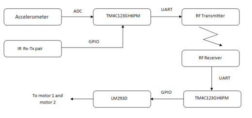
Figure 1: System Block Diagram
The project can broadly be broken down into the following modules :
1. Gesture sensing: In the system block diagram, the accelerometer and the IR Tx-Rx pair together realize the gesture sensing function.
2. Encoding instructions and transmission over RF: The TM4C123GH6PM microcontroller is used for encoding the instruction based on the sensed values of the accelerometer and the IR Tx-Rx pairs. These instructions are transmitted over the RF 433MHz Tx module to the robotic car.
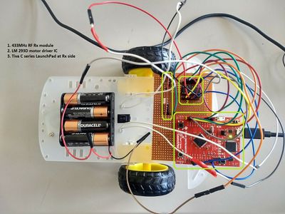
3. Receiving RF signal, decoding the instruction and motor drive: The RF signal is received at the robotic car using the RF 433MHz Rx module. The instructions are then decoded by the host TM4C123GH6PM microcontroller and the motors are accordingly driven.
Each of these modules is discussed in detail later on.
Components Used
TI Tiva C series LaunchPad | TI Tiva C series Launcpad webpage
3-axis Accelerometer
RF 433MHz Tx-Rx module
IR Tx-Rx pair
Motor Driver L293D
Battery 1.5V
Assembled Robotic Car| amazon item page
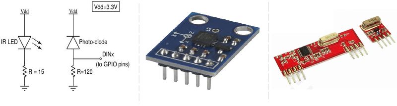
Figure 2(from left to right): IR Tx-Rx circuit, 3-axis Accelerometer and 433MHz RF module
Gesture Sensing
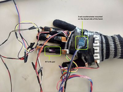
Gesture Sensing is employed using the accelerometer module and five IR Tx-Rx pair(one mounted on each finger).
1. The accelerometer module is mounted on the dorsal side of the hand. This enables us to measure the tilt of the hand and hence is used for direction control purpose. The gestures – left turn, right turn and reverse are implemented by sensing the tilt of hand. The analog data (X, Y, Z) is captured using ADC0 of the TM4C123GH6PM.
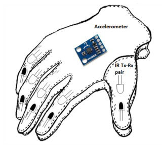
Figure 3: Sensors mounted on hand – an artists view
2. The IR Tx-Rx pair is placed on each finger such that one can detect if the finger is bent or not.
- Thumb finger is used to disable gesture control.
- The index finger is used to put the robotic car in first gear.
- The middle finger is used to put the robotic car in second gear.
- The ring finger is used to apply the brake.
- Rightward tilt of the hand will turn the robotic car in the right direction.
- Leftward tilt of the hand will turn the car in the left direction.
- Tilt in backward direction indicates reverse movement.
Encoding instructions and transmission over RF
Once the digitized accelerometer readings (A_X, A_Y, A_Z) and the IR Tx-Rx readings are known, we encode an instruction that has to be transmitted over the RF module to the robotic car. The encoded instruction is then transmitted as a UART frame over UART1. This serial data is then modulated by the RF 433 MHz Tx module. The RF module does not support a high data rate. As a result, one may have to limit the baud rate of UART to less than a few thousand bps. The UART baud rate was set as shown below:
     UART1_IBRD_R = 1000;        /* IBRD = int(ClkFreq / (16 * 1000)) = int(1000) */
     UART1_FBRD_R = 0;       /* FBRD = round(0.0 * 64 ) = 0 */
The following table shows instruction codes associated with different control operations.
| Instruction | Binary Code | Description |
|---|---|---|
| Operate in First gear | 0000 | The IR sensor mounted on the index finger is used to set first gear. |
| Operate in Second gear | 0001 | The IR sensor mounted on the middle finger is used to set second gear. |
| Disable Gesture Control | —- | Disables gesture control. This is implemented using the IR sensor mounted on the thumb. It is not an instruction and is not transmitted. The instruction transmitted is the last active instruction. The gesture control feature is disabled as long as the thumb finger is bent. |
| Brake | 0101 | The IR sensor mounted on the ring finger is used to stop the robotic car. |
| Right Turn | 0011 | Tilt towards the right is used to turn right. |
| Left Turn | 0100 | Tilt towards the left is used to turn left. |
| Reverse | 0010 | Vertically raised palm is used to set reverse gear. |
Receiving RF signal, decoding the instruction and motor drive
Received RF signal is demodulated by Rx module to obtain encoded instructions. They are sent to the TM4C123GH6PM via UART. Different encoded instructions represent different operations like moving forward, moving backward, turning left, turning right, applying brake, changing gear etc. Based on the decoded instructions, different signals are applied to the motor driver IC LM293D through GPIO pins of TM4C123GH6PM.
- To move forward, two motors are made to rotate in the forward direction.
- For backward motion, two motors are made to rotate in reverse direction.
- To turn left, left motor is made to rotate in the backward direction and right motor is made to rotate in the forward direction.
- To turn right, right motor is made to rotate in the backward direction and left motor is made to rotate in the forward direction.
Different speeds are implemented by using PWM signals of different duty cycles.
Demo
A quick project demo is available on this YouTube link: | YouTube – Gesture controlled wireless car demo
Embedded C code
The embedded C code will be made available shortly on the link:
Challenges Faced
1. The RF module that was used did not support high data rates. As a result, a lot of junk data was obtained at the Rx microcontroller. To resolve this issue, the baud rate of UART1 had to be reduced to 1000bps. One could also opt for a higher quality RF module or other wireless transmission schemes like ZigBee or Bluetooth.
2. Since a large number of sensors are mounted on the hand, it is a bit cumbersome to operate. There would be more value-add if one could reduce the clutter due to the wires.
Acknowledgements
The authors would like to thank Haresh Dagale, Department of Electronic Systems Engineering, IISc for his timely inputs and support. The authors also thank G. Sudharshan and J. Shankarappa for their support. Thanks are also due to some of our seniors – Arjun Balakrishnan, Tessin K. Jose and Sanood Ullattuthodiyil who provided valuable insights when we were stuck.
References
1. Tiva TM4C123GH6PM Datasheet
2. ADC Programming
3. UART Programming
Recent Comments