
Abstract—This report presents the design and implementation of a real-time gesture-controlled drone motor system. The sys-tem utilizes sensor fusion techniques to accurately detect and interpret physical movements, which are then translated into drone navigation commands. We implement both angle-based and rate-based PID control systems to achieve stable flight control. The system features multiple operating modes including gesture control, inertial sensing, and manual control, with comprehensive fail-safe mechanisms to ensure safe operation.Index Terms—Gesture Control, Drone Navigation, Sensor Fusion,PID Control, Motor Control.
I. INTRODUCTION
Gesture-based control systems represent an intuitive inter-face for human-machine interaction, particularly for unmanned aerial vehicles (UAVs). This project develops a comprehensive gesture-controlled drone motor system that allows users to control drone flight parameters through physical movements detected by a SensHub board. The system incorporates sen-sor fusion algorithms, PID control, and motor mixing tech-niques to convert gesture inputs into precise motor control outputs.These systems allow operators to command drone movements simply through hand motions and body gestures,
creating a more natural and accessible interface between humans and aerial vehicles. Gesture-controlled drone tech-nology has revolutionized operations across multiple sectors and continues to find new applications. In photography and filmmaking, these systems enable camera operators to direct drone movements while maintaining focus on composition and creative direction. Search and rescue teams deploy such drones to survey disaster areas while keeping their hands free for other critical tasks. Industrial inspectors use gesture controls to navigate drones through complex structures and confined
spaces that require precise movements. The entertainment and gaming industries have embraced this technology to create immersive interactive experiences where users control drones through physical movements.
II. P ROBLEM S TATEMENT
The project addresses the following key challenges:
1) Real-time Motion-controlled Drone Navigation Sys-tem:
Development of a responsive control system that accurately interprets human gestures
2) Gesture Recognition:
Detection and interpretation of physical movements using the SensHub Board Focus on roll and pitch rotations as primary control inputs
3) Sensor Fusion and Noise-tolerant Motion Analysis:
Implementation of algorithms to combine data from multiple sensors
Filtering techniques to remove noise and improve accuracy
4) Flight Control Unit:
Translation of gestures into directional control com-mands
Active control using PID controllers with MPU9150 and BMP180 sensors.
5) Motor Mixing Algorithm:
Conversion of orientation commands into appropri-ate motor speed adjustments
6) Fail-Safe Logic:
Implementation of safety mechanisms to prevent accidents during operation
III. SYSTEM ARCHITECTURE:
The gesture-controlled drone motor system employs a so-phisticated dual-board architecture to effectively translate hu-man gestures into precise drone movements. The system is built around two interconnected TIVA microcontroller boards that work together to process sensor data, interpret gestures,and control motor output. Fig 2 shows the project setup.
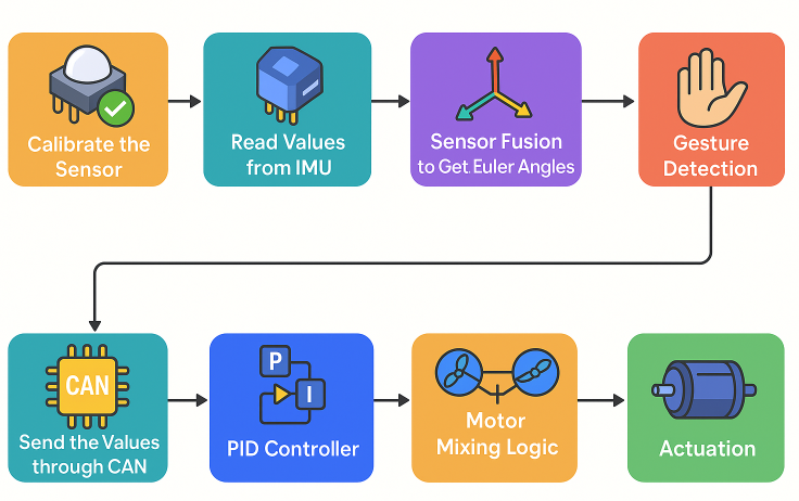
Fig. 1. System Architecture of the Gesture-Controlled Drone Motor System
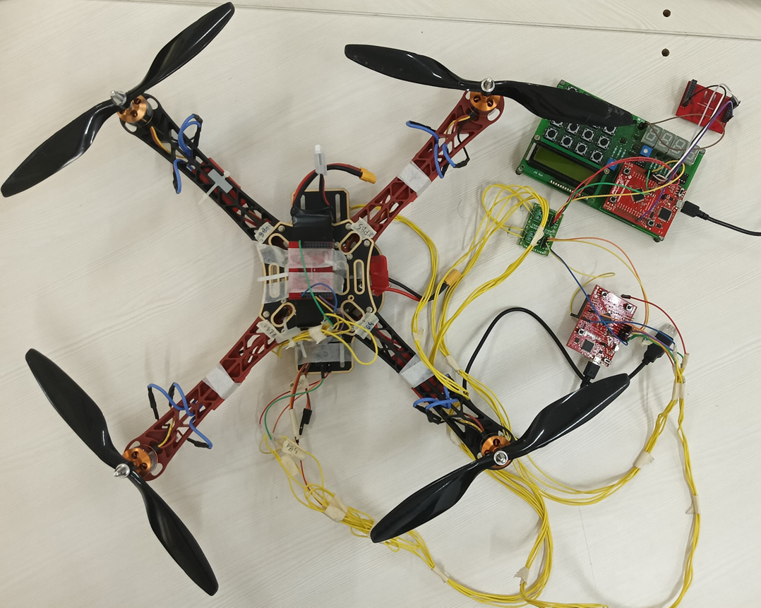
Fig. 2. Complete Setup
A. SensHub Board (Gesture Recognition Unit):
The primary gesture input is captured using a SensHub board equipped with the MPU9150 inertial measurement unit (IMU). This sophisticated sensor package integrates three critical components:
Accelerometer: Measures linear acceleration and gravity vectors
Gyroscope: Detects angular velocity around each axis
Magnetometer: Determines orientation relative to Earth’s magnetic field The SensHub board processes raw sensor data through a sensor fusion algorithm employing the Direction Cosine Matrix (DCM) technique. This fusion effectively compensates for individual sensor limitations and environmental noise, producing accurate roll and pitch angle measurements that represent the user’s hand orientation and movement.After
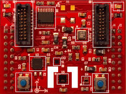
Fig. 3. Senshub Board
initial calibration to establish reference positions, the system continuously monitors deviations from these baseline values. When gesture changes exceed predefined thresholds (> 10 degrees), the system recognizes them as intentional control inputs.
B. Keypad Mode:
Activated by pressing the (1,1) key on the keypad and indicated by a blue LED on TIVA 1, this mode resets roll and pitch values to zero and allows manual modification in 10-degree increments, capped at ±60 degrees. The updated values are transmitted over the CAN bus. The keypad interface enables users to:
Enter or exit keypad mode
Increase/decrease roll or pitch in 10° steps
Return to gesture mode for regular control.
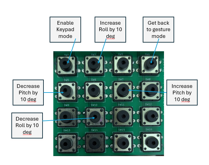
Fig. 4. Eduarm 4×4 Keypad
C. Communication and Control Flow:
The calculated roll and pitch values are transmitted from the gesture recognition unit to the drone controller board via
a CAN (Controller Area Network) bus. This robust communi-cation protocol ensures reliable data transfer between the two microcontroller systems with minimal latency.
D. Drone Controller Board:
The second TIVA board serves as the drone’s flight con-troller. This board:
1) Receives gesture commands (desired roll and pitch an-gles) from the CAN bus
2) Collects real-time orientation data from its own onboard IMU sensor
3) Compares desired orientation (from gestures) with actual orientation (from drone IMU)
4) Processes these values through either Angle PID or Rate PID control algorithms
5) Applies motor mixing logic to translate control signals to individual motor commands
The motor mixing algorithm calculates the appropriate power distribution across the drone’s four motors (in X con-figuration) to achieve the desired orientation. This involves increasing or decreasing specific motor speeds in complemen-tary patterns to generate the necessary torque for pitch, roll, and yaw movements.
1) Operational Modes: The drone controller implements three distinct operational modes to accommodate different control scenarios:
Gesture Mode: In this mode, user gestures are in-terpreted via the handheld SensHub board, and corre-sponding angle setpoints are sent to the drone through CAN messages. The measured angle remains zero during ground testing, producing a differential that drives the PID controller. Gesture mode allows direct control over motor speeds — including incremental steps, individual and collective control, and emergency stop (indicated by a red LED). A white LED signifies this mode is active. Gesture mode also enables switching between inertial and gesture-based control as well as between Angle and Rate PID modes.
Rate PID Mode: Indicated by a green LED, this mode focuses on angular velocity rather than position. Setpoints are received via UART, and measured angular rates come from the drone’s SensHub IMU. The PID controller calculates motor adjustments based on rotational rate error, enabling quick and responsive flight dynamics. Barometric altitude data from the BMP180 enhances vertical control. Outputs are processed through the motor mixing logic to drive PWM signals for each motor.
Angle PID Mode: Indicated with a yellow LED, this mode uses angular position errors to determine motor outputs. Desired roll, pitch, yaw, and height values are set via UART or gesture input, and the measured values come from the onboard IMU. This mode enables stable flight by minimizing positional error through the PID algorithm. It is ideal for hovering and smooth flight. Motor outputs are
generated through mixing logic and translated into PWM signals.
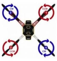
Fig. 5. X Configuration Drone
The system transitions between these modes exclusively through UART commands, with appropriate safeguards imple-mented to ensure smooth mode transitions. This centralized command interface provides a consistent method for opera-tional mode selection and prevents mode conflicts during flight operations.
E. Output Control:
The final PWM (Pulse Width Modulation) signals gener-ated by the controller board are sent directly to the drone’s Electronic Speed Controllers (ESCs), which regulate power to the four A2212-1000KV motors. This complete control chain—from hand gesture to motor rotation—enables intuitive real-time navigation of the drone through natural human movements.The architecture incorporates multiple failsafe mechanisms and operational modes, allowing for smooth transitions be-tween gesture control, manual operation, and various PID con-trol strategies to ensure safe and responsive flight performance under different conditions.
F. Fault Detection, Isolation, and Recovery (FDIR):
The system implements comprehensive safety mechanisms to prevent potential hazards and ensure reliable operation:
Emergency Stop: Switch 1 triggers an interrupt that immediately stops all motors, activates the red LED indicator, and forces the system into manual mode.
Hovering Mode: Switch 2 triggers an interrupt that sets all motors to hovering speed, activates the sky blue LED indicator, and switches to manual mode, allowing the drone to maintain altitude while awaiting further commands.
Additional Safety Features:
Debounce logic for switch inputs to prevent false triggers
Upper and lower speed limit clamping to avoid dangerous motor operation
Mode transition restrictions:
Angle PID to Rate PID transitions (and vice versa) only permitted through manual mode
Inertial to gesture mode transitions (and vice versa) only permitted through manual mode
Desired value updates via CAN messages restricted to gesture mode only
These safety mechanisms ensure that the system maintains controlled operation even in exceptional circumstances, pre- venting unintended behaviors and protecting both the drone and its environment.
IV. HARDWARE CONFIGURATION:
A. Drone Configuration
X configuration layout
Four A2212-1000KV motors
Four 1045 propellers
Four 30A Electronic Speed Controllers (ESCs)
B. System Components
Control Inputs:
Sensors on I2C interface
UART interface
Keypad buttons
Switches
•System Outputs:
LCD display
7-segment display
PWM control signals
Motor speed control
C. Primary Hardware:
BOOSTXL-SENSHUB board
TIVA microcontroller board
Drone kit with motors, ESCs, and frame
V. S YSTEM V ERIFICATION:
To validate the drone’s functionality, various tests were conducted using manual, gesture-based, and keypad-based
inputs:
Gesture and Keypad Modes: Roll and pitch values were modified incrementally, and the corresponding motor speed variations were monitored via PWM data printed over UART. Angle and Rate PID Modes: Desired setpoints were pro- vided through UART, and motor responses were verified. Additionally, the drone was physically tilted to induce changes in measured IMU angles, thereby testing the controller’s
feedback response.The table below summarizes the results of these tests, confirming correct motor behavior under all tested conditions.
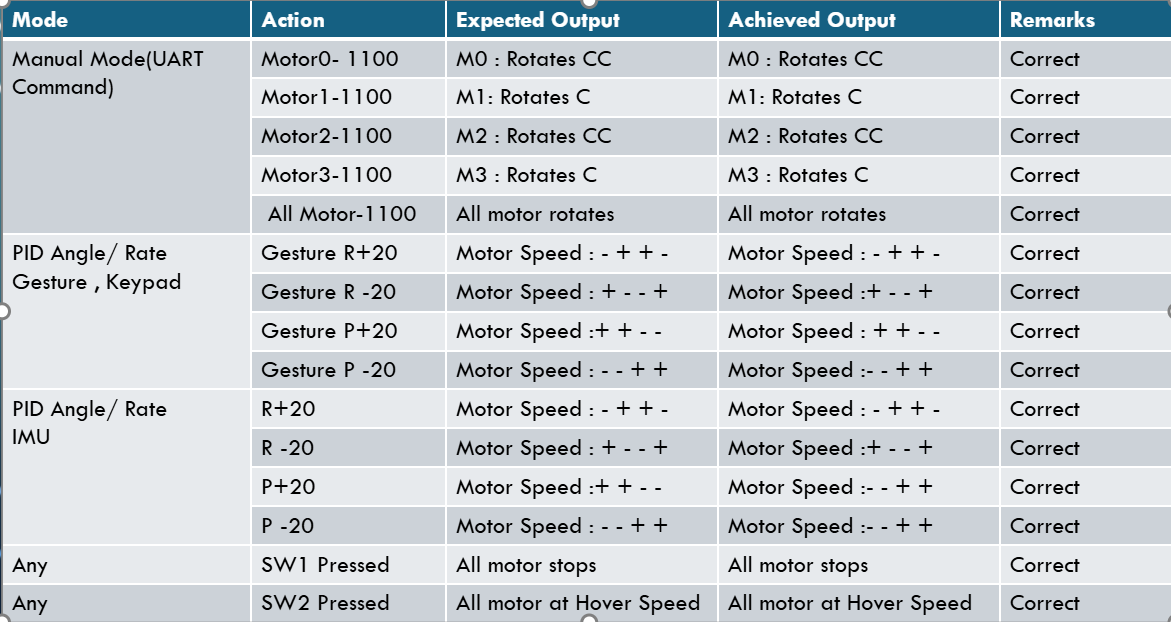
Fig. 6. Eduarm 4×4 Keypad
VI. CONCLUSION AND FUTURE SCOPE:
The Gesture Controlled Drone Motor System is successfully implemented using two TIVA microcontrollers and two inertial sensors. The system integrates various interfaces, including I2C, UART, CAN, and PWM, to enable real-time motion control of the drone. The addition of safety features such as fail-safes and motor speed limits ensures reliable operation. The PID control algorithms (both angle and rate) help in achieving precise and stable flight, allowing for intuitive gesture-based control. Future enhancements could focus on the development of a more robust hardware setup with improved wireless communication for greater flexibility and range. Additionally, refining motor and PID calibration will allow for better accuracy and responsiveness, enhancing the overall system performance.
Recent Comments