
Generating PWM with Microcontroller using Timer/Counter
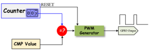
The basic idea to generate PWM signal is using a counter (or timer), a CMP (compare) value, and a digital output pin. The counter continuously counts to up or down, and is compared with CMP value. The digital output (PWM) will be changed when the counter matches the CMP value, or when counter resets. It can be implemented by software or hardware. Most of microcontrollers already have hardware modules that can generate PWM signal after initialize the registers.
PWM Timer
The PWM timer in the microcontroller runs in one of two modes: Count-Down mode or Count-Up/Down mode.
In Count-Down mode, the timer counts from the Period (LOAD) value to zero, goes back to the Period (LOAD) value, and continues counting down. In Count-Up/Dow mode, the timer counts from zero up to the Period (LOAD) value, back down to zer, back up to the Period (LOAD) value, and so on. Generally, Count-Down mode is used for generating left- or right-aligned PWM signals, while the Count-Up/Down mode is used for generating center-aligned PWM signals.
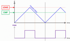
Center-Aligned PWM
A center-aligned PWM implements the PWM differently from all of the other modes. The PWM timer is configured counting-up and -down mode. The counter starts at zero and count up to the Period (LOAD) vlaue, and when the Period (LOAD) value is reached, the counter starts counting back down to zero. In this mode, the Period (LOAD) value is actually half of the period of the final PWM output.
- A single compare (CMP) value, which ciontains the duty cycle value, is constantly compared with the PWM timer (COUNTER) value. When the timer (COUNTER) value is less than the CMP value, the PWM output signal is deasserted.
- When the timer (COUNTER) value exceeds or equal to the CMP value, the PWM output signal is asserted. When the timer (COUNTER) value reaches the Period (LOAD) value, the timer starts counting down to zero.
- When the timer (COUNTER) value is less than or equal to the CMP value, the PWM output signal is deasserted, and the process repeats.
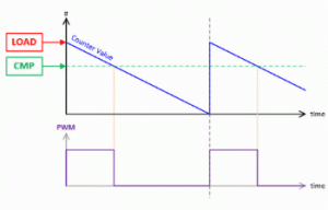
Left-Aligned PWM
To create the Left-Aligned PWM, a PWM timer counts downward from a specified maxmimum value, called Period (LOAD) value, to zero. When the timer counts to zero, the Period (LOAD) value will be reloaded to the timer and continue to count down..
- When the timer (COUNTER) value is greater than the CMP value, the PWM output signal is asserted.
- When the timer (COUNTER) value is less than or equal to the CMP value, the PWM output signal is deasserted.
- When the timer counts to zero, the timer will reload the value from Period (LOAD) value.
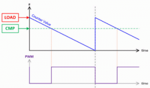
Right-Aligned PWM
To create the Right-Aligned PWM, the PWM timer still runs on counting-down mode
- When the timer (COUNTER) value is greater than the CMP value, the PWM output signal is deasserted.
- When the timer (COUNTER) value is less than or equal to the CMP value, the PWM output signal is asserted.
- When the timer counts to zero, the timer will reload the value from Period (LOAD) value, and the process repeats.
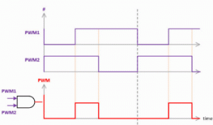
Dual-Edge PWM
A dual-edge PWM uses two different aligned PWM, one is right-aligned and another is left-aligned. Those two PWMs are connected to an AND gate, the output is the dual-edge PWM signal.
Recent Comments