
Introduction
Project titled “Function generator through GLCD” and real time plotting of waveforms on matlab aims to generate different waveforms (i.e sin, tri, square) with multiple channels. We can change or select the frequency and amplitude of the waveform at any time. Two different channels are there so that we can generate different waveforms on different channels. (i.e sine wave in channel 1 whereas triangular wave in channel2) and change their frequencies and amplitude separately in two ways. First way of changing the frequency and amplitude is giving appropriate command through UART console window and another option is selectin the frequency and amplitude of a particular channel through GLCD screen.
Basic Features included:-
Selection of different waveforms for different channels.
Frequency and amplitude selection for a particular channel.
Coarse and fine tuning of amplitude and frequency.
Zoom in and Zoom out of waveform.
Real time plotting of waveform in matlab.
Switching back to previous or home screen at any instance.
Components Required:
TM4C123GH6PM
BOOSTXL – K350QVG-S1 Kentec QVGA Display
Interfacing Modules
1. Touchscreen Graphic Lcd Display
We have used BOOSTXL – K350QVG-S1 Kentec QVGA Display in our project. It is an easy-to-use plug-in module for adding a touch screen color display to our Launchpad
design. we use this BoosterPack to start developing applications using the 320 x 240 pixel SPI controlled TFT QVGA display with resistive touch screen.
Key Features
1. Kentec TFT LCD (part number: K350QVG-V2-F)
1. 3.5-inch QVGA (320×240 resolution)
2. SPI communication
3. 4-wire resistive touch screen
4. White LED backlight
2. LED backlight driver circuit
3. Complies with the BoosterPack standard for use with 20- and 40-pin
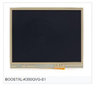
Figure 1.1 GLCD Display
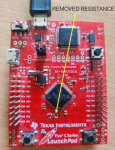
Figure 1.2 GLCD Display over launchpad board
Let us look into functionalities of each screen separately.
1. HomeScreen –
Here we have eight buttons on our home screen.
For Channel 1:-
Here we can select any of the three waveforms by pressing the respective button (i.e sine, square, triangular) that we want to observe in channel 1. By default, sin wave will be displayed in channel 1.
For Channel 2:-
Here we can select any of the three waveforms by pressing the respective button (i.e sine, square, triangular) that we want to observe in channel 2. By default, sin wave will be displayed in channel 2.
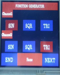
Figure 1.3 homeScreen on GLCD display
2. Frequency and Amplitude select for channel 1:-
Here we are having two different types of frequency and amplitude tuning mechanism Coarse Frequency tuning:
In this tuning mechanism, frequency will increase or decrease by 5 hz on every press ofincrement and decrement button.
Fine Frequency tuning:
In this tuning mechanism, frequency will increase or decrease by 1 hz on every press of increment and decrement button.
Coarse Amplitude tuning:
In this tuning mechanism, Amplitude will increase or decrease by 1V on every press of increment and decrement button.
Fine Frequency tuning:
In this tuning mechanism, amplitude will increase or decrease by 0.1V on every press of increment and decrement button.
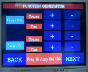
Figure 1.4 Freq and amplitude select channel 1 Screen on GLCD display
3. Frequency and Amplitude select for channel 2 :-
Here we are having two different types of frequency and amplitude tuning mechanism Coarse Frequency tuning:
In this tuning mechanism, frequency will increase or decrease by 5 hz on every press of increment and decrement button.
Fine Frequency tuning:
In this tuning mechanism, frequency will increase or decrease by 1 hz on every press of increment and decrement button.
Coarse Amplitude tuning:
In this tuning mechanism, Amplitude will increase or decrease by 1V on every press of increment and decrement button.
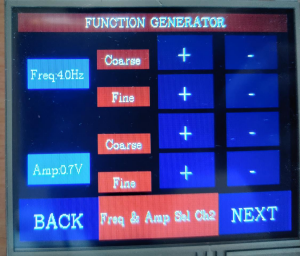
Figure1.5 Freq and amplitude select channel 2 Screen on GLCD display
4. Display Waveform Channel 1:-
In this screen, we are trying to display the waveform selected for channel 1 with corresponding frequency and amplitude as selected in frequency and amplitude select screen channel 1.
We can change the frequency and amplitude of waveform by giving command through UART console window.
For e.g if we have to change the frequency of waveform to 5Hz. Then simply write “1F5”.
Here ‘1’ implies channel 1, ‘F’ implies frequency and ‘5’ is the value of frequency in Hz.
For e.g if we have to change the amplitude of waveform to 2.5V. Then simply write “1A3”.
Here ‘1’ implies channel 1, ‘A’ implies amplitude and ‘2.5’is the value of Amplitude.
If the entered command is not recognized by the system then it will show an error message.
Home button: –
This button will redirect us to home screen. So that we can switch to another waveform.
Next button: –
This button will redirect us to display waveform channel 2. So that we can observe the
waveform in channel 2.
Back button:-
This button will redirect us to frequency and amplitude select channel 1. So that we can select required amplitude and frequency through touch screen display.
Zoom in button:-
This is an inbuilt button which is present but not visible on the screen. If we press the left side of the screen then the given waveform will be zoomed in.
Zoom in button :-
This is also an inbuilt button which is present but not visible on the screen. If we press the right side of the screen then the given waveform will be zoomed out.
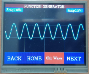
Figure 1.6 Display channel waveform1 on GLCD display
Challenges Faced
The following challenges are faced while working on the project.
While interfacing the GLCD along with UART, there was a problem with system clock. UART was not working properly with system clock, hence we need to write
0x05 in UART_CC_R register so that it uses the same clock as used by GLCD.
While handling the interrupt for systick timer, we can not write the entire code in ISR. Because it will take some time to execute the ISR. Hence our touch screen
functionality will gets disturbed. So it’s better to set a flag in systick handler and write the corresponding ISR in main function instead of systick handler.
Do not forget to enable the FPU related functions. This will lead to improper working of push buttons on GLCD.
Systick handler interrupt time to access two different samples of an array can not be reduced beyond 1ms. Because maximum UART baud rate is 115200. Hence we
can increase frequency upto a certain extent.
References
1. BOOSTXL-K350QVG-S1 QVGA Display BoosterPack™ Plug-in Module –
http://www.ti.com/lit/ug/slau601a/slau601a.pdf
2. BoosterPack (BOOSTXL- K350QVG-S1) –
http://www.kentecdisplay.com/uploads/soft/Products_spec/BOOSTXL-
K350QVG-S1_UserGuide_04.pdf
3. TivaWare™ Peripheral Driver Library (User Guide) –
http://shukra.dese.iisc.ernet.in/emsys/tivac/ek-
tm4c123gxl/TivaWare_Peripheral_Driver_Library__Users_Guide.pdf
4. Tiva™ TM4C123GH6PM Microcontroller(Datasheet)-
http://shukra.dese.iisc.ernet.in/emsys/tivac/ek-
tm4c123gxl/TM4C123GH6PM_Microcontroller_Data_Sheet.pdf
5. Tiva™ C Series TM4C123G LaunchPad Evaluation Board(User’s Guide) –
http://shukra.dese.iisc.ernet.in/emsys/tivac/ek-
tm4c123gxl/TM4C123GH6PM_Microcontroller_Data_Sheet.pdf
6. TivaWare™ Graphics Library(User’s Guide) –
http://www.ti.com/lit/ug/spmu300d/spmu300d.pdf
7. TivaWare ™ Graphics Library Display Drivers –
http://www.ti.com/lit/an/spma055/spma055.pdf
code details find here Final Function Generator code
Recent Comments