
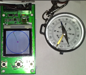
This page describes the e-Compass Project, which is a part of the Embedded Systems-1 course. The aim of the project is to build display Electronic Compass using data acquired from a Magnetometer on a Graphics LCD Screen. The acquisition and Display is done using the STM32L Discovery Low Power platform which uses the Cortex M3 processor.
STM32L Discovery Board Details
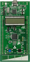
STM32L Board
The STM32L Discovery board is based on an STM32L152RBT6 and includes on-board ST-Link/V2 debug interface. As can be seen from the Picture, most of the General Purpose I/Os (GPIOs) are brought out for use towards the sides of the board.
The main features of the board which were used in this project are:
- The external 3V and 5V supply pins which can be used to provide power to LCD and Magnetometer addon boards
- The GPIO ports brought out to sides of the board
- Built-in SPI or USART module (which can be used for LCD Control)
- Built-in I2C Module (used for Magnetometer Interface)
Nokia 6610 LCD Add-On board
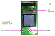
LCD Add-On Board
The LCD add-on board consists of the following features:
- Provision to connect Nokia 6610 Graphics LCD
- A joystick(4 direction and a push) and two push-buttons.
- MicroSD card slot
The joystick and MicroSD slot are not used in this project.
Magnetometer Add-On board
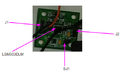
Magnetometer Add-On Board
The Magnetometer add-on board has the following features:
- 3-axis Magnetometer
- 3-axis Accelerometer
Only the Magnetometer is used presently in this project.
Interconnection Details
The Magnetometer Add-On Board has File:LSM303DLM Datasheet.
which has both 3-axis magnetometer and 3-axis accelerometer. The interface to this IC is via I2C. The Magnetometer address is 0x18. The I2C1 interface in STM32 board is used for this. The board is powered using 3V Ext Output from the STM32 Board
Thee LCD Add-On Board Pin Out for L.J1 connector (20-pin) is as below:
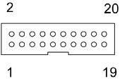
LCD Add-On Board Connector Pin Out
The following are the connections to be made between the STM32 Board and the Add-On Boards:
Magnetometer Board: M
STM32 Board : S
LCD Board: L
| Sl.No. | Source | Destination | Remarks |
| 1. | S.EXT_3V | M.J1.1 | 3V Supply to Magnetometer Board |
| 2. | S.GND | M.J1.2 | GND to Magnetometer Board |
| 3. | S.PB9 | M.J2.2 | I2C1-SDA of STM32 to SDA of Magnetometer Board |
| 4. | S.PB8 | M.J2.1 | I2C1-SCL of STM32 to SCL of Magnetometer Board |
| 5. | S.EXT_3V | L.J1.1 | 3V Supply to LCD Board |
| 6. | S.EXT_5V | L.J1.12 | LCD Backlight |
| 7. | S.GND | L.J1.2 | GND for 3V Supply for LCD |
| 8. | S.GND | L.J1.14 | GND for 5V Supply for LCD Backlight |
| 9. | S.PB13 | L.J1.5 | SCLK of STM32 to SCLK of LCD Board |
| 10. | S.PB15 | L.J1.3 | MOSI of STM32 to MOSI of LCD Board |
| 11. | S.GND | L.J1.4 | GND the CS of LCD Board to select it always |
Notes:
1.The Jumper SJ1 in Magnetometer Add-On Board can be any position as it is accelerometer address selection.
2. The pull up for the I2C interface is already in the Magnetometer Add-on board and so no extra pull-up is required.
LCD controller and communication details
![]()
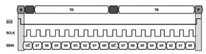
The LCD used has in-built controller of S1D15G00 series which communicates with SPI protocol, with 9 bit data width. The control command or data sent to the controller is recognized using the first bit on the line. The remaining 8 bits are received and interpreted with MSB first logic. The colour information of each pixel is sent in 12 bit format with each pair of pixels packed in 3 bytes (as shown). A software library of basic display functions can be found in the Tutorial by James Lynch. The SPI protocol can be implemented using GPIO pins, with bit-banging with appropriate timing. The controller has a wrap-around increment logic, which can be used to address pixels in a specific area using control word PASET and CASET, so that the whole screen need not be refreshed each time. BMP images can also be displayed if the size of the image can fit in the flash memory of the STM32L board.
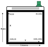
LCD Pixel Address
As the controller uses the already described 12 bit format and byte-packing, appropriate .bmp to hex array conversion is needed before using the image in the code.
The co-ordinates of the pixels on the Nokia-6610 LCD panel which uses the above described controller, is shown in the figure. The horizontal axis increases the y co-ordinate and vertical, the x co-ordinate. Contrast of the lC can be adjusted by appropriate command to the controller which can be found in the same tutorial mentioned above, or the datasheet of the controller Bit-banging on GPIO can give a speed of 1.25 MHz max. This speed is fast enough to render frames so that the motion of an pbject looks continuous to the human eye. However, the speed is not as fast as a dedicated SPI perpheral, so that timer need not be used to give the needed delay for adjusting the frame rate. Hence, a continuous rendering of pixels has been performed, to give the motion of the ball and bat. The timing diagram of the communication link is shown in the figure.
The GPIO bit bang needs the following steps :
     1. Reset Clock pin
     2. Set Data pin high for data, and low for command
     3. Set Clock pin
     4. Reset Clock pin
     5. Put valid bit on Data pin
     6. Set Clock pin
     7. Perform last three steps a total of 8 times
Loop unrolling, and direct register write at GPIO increases the speed of communication by a large amount as this is the hotspot of the code.
LED Toggling
The STM32 Board has two LEDs under user control. Port B is connected to this. The LEDs are alternate lighted in the event of a significant change in the reading from the magnetometer (corresponding to the Magnetometer Board movement). This feature helps is quick troubleshooting as it indicates whether data is properly received from the magnetometer board via the I2C interface.
Software Algorithm
The following are the sequence of steps done in software to acquire the data from Magnetometer via I2C and
1. Configure System clocks - RCC_Configuration()
2. Initialize GPIOs - GPIO_Init()
3. Initialize LCD - Init_LCD()
4. Render a Circle of Radius 65 (centre of LCD screen of 132 x 132 size) for the e-Compass boundary - LCDSetCircle
5. Initialize LED - LED_Init()
6. Configure I2C  - I2C_Configuration()
7. Put Magnetometer in Continuous acquisition mode  - write_LSM303DLH()
8. Set Data Output Rate to 75Hz by setting 0x18 value in the CRA_REG_M Register of Magnetometer - write_LSM303DLH()
9. Start an infinite loop that does the following:
   Calculate x from 65+56*cosine and y from 65+56*sine
   Render a Rectangle in centre, Line with small circle in the tip for the Magnetic North Pointer
   Read the registers OUT_X_H_M (03), OUT_X_L_M (04h), OUT_Z_H_M (05), OUT_Z_L_M (06h), OUT_Y_H_M (07), OUT_Y_L_M (08h)
   Separate out the values into x,y and z
   Check whether the x,y,z values have changed by 50 or more by taking change in x,y,z and summing them up. This is used for LED Toggling.
   Average x,y,z values using the formula new_x = (x_average * 0.8) + (x_current_value * 0.2).This gives smoother Pointer Movement.
   Compute sin and cos of the angular displacement of pointer using cosine = xav/(sqrt(x^2 + y^2)) and sine = yav/(sqrt(x^2 + y^2))
Points to be Noted
1. The LCD Add-on board has an LCD Reset. This is done using a Resistor and Capacitor. This line has to be made Low and High before
   sending the LCD initialization commands. So every time the Program is downloaded to the Flash Memory of STM32, Remove the USB connector
   of STM32 Board from PC and reconnect it. This resets the LCD as 3V supply is from STM32 Board and code execution starts after LCD Reset.

2. Multiple Ground Connections is recommended for the LCD Add-On Board.

3. The Magnetometer Registers in the Register Memory of LSM303DLM IC are in the Order "X, then Z and finally Y".

4. Acknowledgement of the I2C interface has to be disabled.

5. Interconnecting Wire Lengths should be as small as possible, especially for the SPI Interface.

6. Registers marked "reserved" in datasheet of LSM303DLM SHOULD NOT be written into during write_LSM303DLH(). A wrong address results
   in Permanent IC Malfunction.

7. The schematic of Magnetometer Add-On Board shows Mag address as 0x18. It is in fact 0x3D or 0x3C for Read and Write respectively
   (refer LSM303DLM datasheet)
Source Code
The Source Code for use with Keil uVision can be found in moodle
Future Enhancement
Currently, tilt compensation is not implemented in this project. Future work can include implementing a tilt-compensated e-Compass. The following application Note provides information on implementation using magnetometer and accelerometer: File:Tilt_Compensated_e-Compass_App_Note
Project Team
- Manoj R.
- Sijomon Parakkal
Recent Comments