
Project Concept
To make a drawing tool using CNC breakout board. We should be able to
give any image as input and tool should draw that image for us. We have
used two stepper motors for X and Y axis movement. Stepper motors are
used for precise movement along X and Y axis. For Z axis, we have used
servo motor.
Implementation Details
Following steps are performed to draw the sketch:
1. First, we need the vector image as input for the tool. We can either
download any test image from the internet or if we want the tool to
draw any photograph, then we need to convert that photograph to
vector image using any image processing tool. We did the conversion
part in Adobe Photoshop.
2. In second step, we have used Inkscape to obtain the Gcode of that
image. Gcode contains the coordinates of the pixels from the image.
These coordinates will be later used by the TIVA board to draw the
image. Here Inkscape generates three types of commands. First, M300
S30 which means pen down. Second, M300 S50 which means pen up.
Third, G1 command, which is used to draw straight line. Fourth,
G2/G3 commands, which are used to draw the clockwise/anti-clockwise
arc.
3. G2/G3 commands aren’t supported by our TIVA code. So, we first
need to convert G2/G3 commands to G1 commands. Which means,
arcs will be approximated by many small straight lines. We used open
source tool Arc breaker to do this approximation for us.
4. Finally our Gcode is ready. We have developed one tool using Process-
ing to send this Gcode to TIVA board over UART. Processing is an
Open-source software which lets us develop softwares with ease.
5. After sending the Gcode TIVA board will start drawing the image for
us. Our TIVA code understands three types of commands. Pen up,
pen down and draw straight line (G1). Based on input received over
UART it will draw the sketch
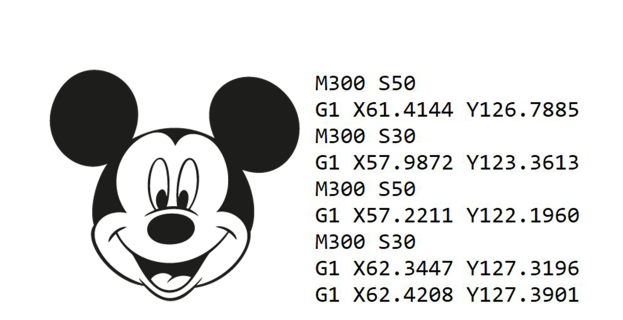
Figure 1: Example image and generated Gcode (only small part of Gcode is included here. Entire Gcode is quite large)
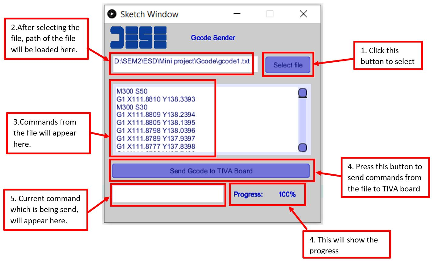
Figure 2: GUI created to send Gcode commands to TIVA board
Wiring Diagram:
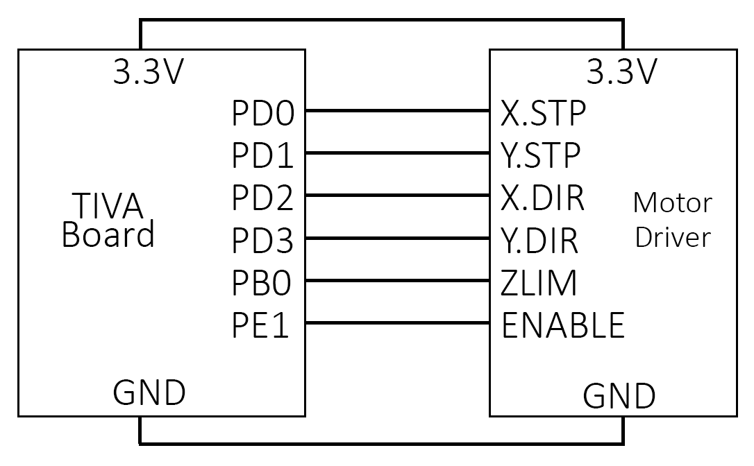
Figure 3: Wiring diagram
Results:

Figure 4: Image drawn by the tool
code:CNC_drawing_tool_tiva_code
Recent Comments