
This page contains the documentation of the Closed loop Speed Control of Induction Motor which is done as a part of the Embedded Systems-1 course. The project is done using the Tiva C Series Launchpad.
Introduction
Induction motor is one of the most widely used motor because of its ruggedness, very less maintenance and non occurrence of spark due to the absence of commutator and brushes. 3 phase induction motor is more popular because of its self starting capability. Normally induction motor is operated at a constant speed(or a desired speed) irrespective of the variation in load torque. The most popular methods to control the speed of the induction motor are vector control and scalar control (v/f control). Speed control means that whatever be the load condition (within the rated value) of the motor, it should be made to track the desired reference or set speed. In this project v/f control scheme is implemented to control the speed of the induction motor using Tiva C series launchpad.
Functional Block Diagram
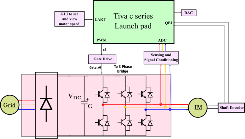
Functional block diagram
For v/f speed control we require a variable-voltage variable-frequency power source, which is not readily available. The readily available sources are fixed frequency voltage available from grid or a DC voltage from a battery. So, in order to make the required AC voltage at required frequency we use a 3 phase voltage source inverter(VSI). A VSI converts constant DC into variable voltage and variable frequency AC voltage. If the available source is grid, then grid voltage is rectified and then fed into this inverter. Instead if a battery is used then with the help of a DC-DC converter the battery voltage is converted to required DC voltage level and is then fed to the inverter. To control the output of this three phase inverter, gating pulses should be given to the corresponding switches of the inverter. Speed and currents of the motor will be sensed and will be processed as per the control scheme used and the required pwm pulses will be generated. These pulse will be in the signal level. To interface with the inverter, gate driver modules are used. For sending the speed reference command and knowing the present speed a GUI is developed. To view and study the various signals in the microcontroller a dual channel DAC is also interfaced.
Control Block Diagram
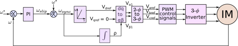
Control block diagram
The block diagram shown in figure presents an overview of the closed loop speed control of induction motor using v/f control scheme. Here reference given is speed, which is compared with the actual speed of the motor and the error is used to drive a PI controller, the output of which will give slip speed. The sum of reference speed and slip speed will give synchronous speed. From the synchronous speed, the required voltage is generated so as to keep the v/f ratio constant. The three phase modulating waveform is generated using synchronously rotating dq reference frame to 3 phase transformation. In order to increase the DC bus utilisation, space vector modulation PWM is used.
Hardware description
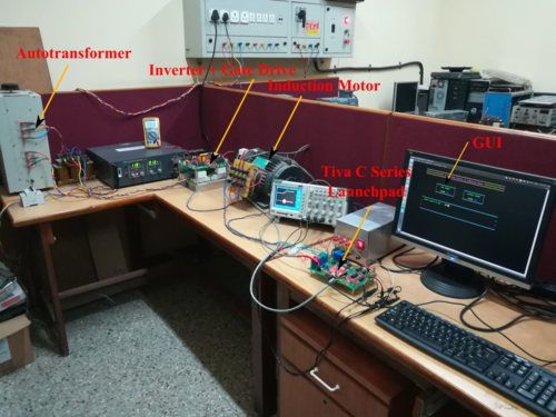
Hardware Setup
Power section
DC source
3 phase grid voltage is rectified using a diode bridge rectifier with capacitive filter in order to make the DC link for the inverter.
Three phase inverter
Since we require 3 phase voltage for the induction machine, a three leg, two level inverter configuration is employed . It comprises of six IGBT – diode pairs, ie two IGBT – diode pairs per leg. These IGBTs are controlled by applying appropriate PWM pulses.
Induction motor
415V, 3.7kW, 1430 rpm 3 phase squirel cage induction motor is used for the experimental setup.
Graphical User Interface
Sensing and signal conditioning
Speed sensing
Speed is sensed by using a shaft encoder coupled to the machine shaft, it gives 3 square wave pulses as output, namely A, B, Z. A and B pulses will give 2048 pulses per revolution and are phase shifted by 90 degrees. Depending on the direction of rotation of the motor, one pulse will be leading the other by 90 degrees. By sensing the lead pattern one can recognize the direction of rotation. Z pulse will give 1 pulse per revolution. These three signals are fed to QEI pins of the Tiva c series launch pad to compute the speed of the machine.
Current sensing
Three phase motor currents are sensed using hall effect sensors. The signal obtained will be bipolar and will be having swithching frequency components and their harmonics, apart from the fundamental component. The high frequency components are filtered out with the help of Sallen Key filter. Now to make the signal to be unipolar so that it fits into the range of the ADC(0 – 3.3V), this filtered signal is level shifted by (3.3/2)volts.
Control Section
Tiva C series Launchpad is used for the project. The sensed currents as well as the encoder output signals are taken into the microcontroller, processed according to the control scheme and the appropriate PWM pulses are outputted.
Communication Section
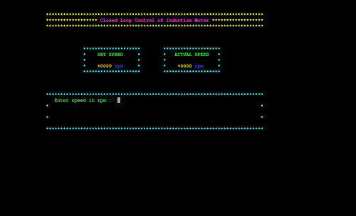
A Graphical user Interface (GUI) has been developed for the purpose of communication between the user and the microcontroller. The UART module of the Tiva C series Launchpad is utilised for this purpose. The GUI takes the reference speed command from the user. It also displays the actual speed of the motor.
Monitoring and Display
Two Dual channel, 8-bit, parallel Digital to Analog converter(DAC) are used for the purpose of monitoring the various signals inside the microcontroller. This will be especially useful for studying the profile of the various signals and also for tuning the PI controller. The DAC outputs are viewed with the help of a DSO.
Modules Initialised in Tiva C Series Launchpad
1.PWM:This module is configured in Up-Down counter mode to run at a frequency of 2.5KHz. PWM interrupt is also enabled. The entire control code is run in the PWM Interrupt Handler.
2.QEI:This module is used for the measurement of the motor speed. It takes the encoder signals as input and gives the speed in rpm along with the direction of rotation of the motor.
3.UART:Configured for a baud rate of 115200 with one stop bit and no parity bit.An interrupt will be triggered after the recieval of each data chunk.
4.ADC:3 ADC channels are utilised for motor current measurement.
5.PLL:This module is configured to scale up the clock from 16MHz to 80MHz.
6.GPIO:10 GPIO pins are configured as output and used for DAC output.
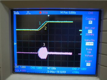
1.Reference speed 2.Actual speed 3.Phase current
Results
Recent Comments