
Project overview
❑ Ac to dc converters is an essential part of many power electronics systems such as battery chargers, dc link motor drives inverter, rotor circuit of DFIG for wind systems.
❑ In three phase active rectifier MOSFET or IGBT are used. These switches can be controlled by sinusoidal PWM so the average voltage between the two MOSFET is sinusoidal. The converter
can be controlled such that it can give input power factor of unity.
❑ Vector Control can be used for the control of the rectifier. In vector control the three phase quantities can be converted into equivalent two-phase dc quantities. These d-q quantities can be
controlled by PI controllers. By controlling the active power, the DC voltage can be controlled.
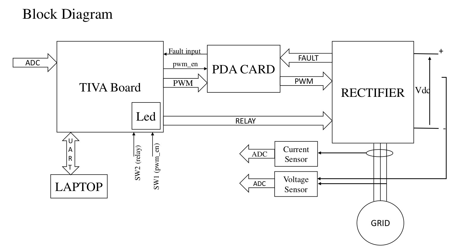
❑Project aim is to make a close loop controller for a three-phase grid connected rectifier using Tiva TM4C123GH6PM controller.
Embedded Features
• System Clock frequency changed from 16 MHz to 80MHz
• Clock enable for GPIOs, PWM0 module, ADC0.
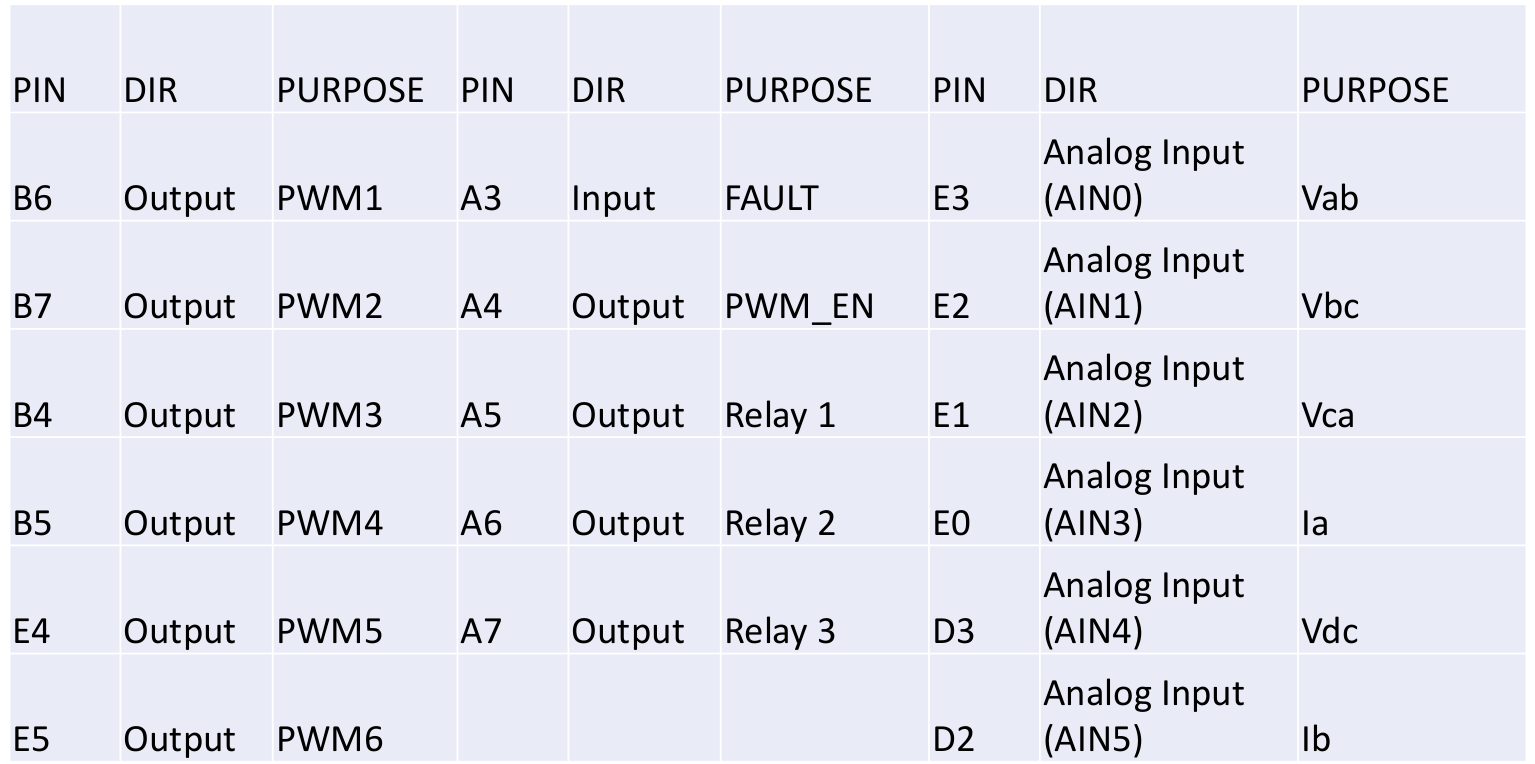
• GPIOs configuration
• ADC Configuration: Sample Sequencer 0 is used.6 adc inputs. ADC is triggered by
PWM0’s Gen 0 interrupt.
• PWM Configuration: 3 Generator are used for making 6 PWM signals. The PWM
frequency is set to 2.5kHz. One generator gives two complementary PWM signals with a
dead-band of 5us. PWM interrupt is enabled and this interrupt also generator trigger signal
for ADC conversion.
• In PWM ISR adc starts conversion. After finishing 6 conversions ADC raise interrupt flag.
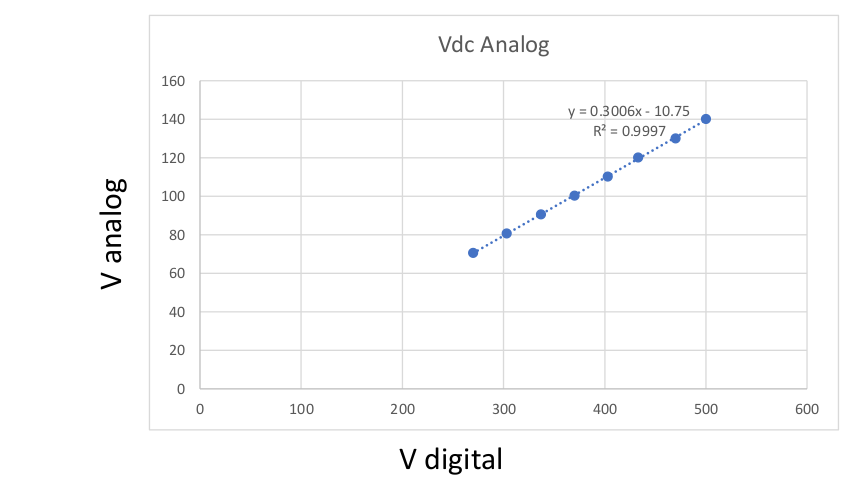
ADC calibration and filtering using Butterworth filter.
• Converting ADC data to actual quantities.
• Implementations of Different Control loops.
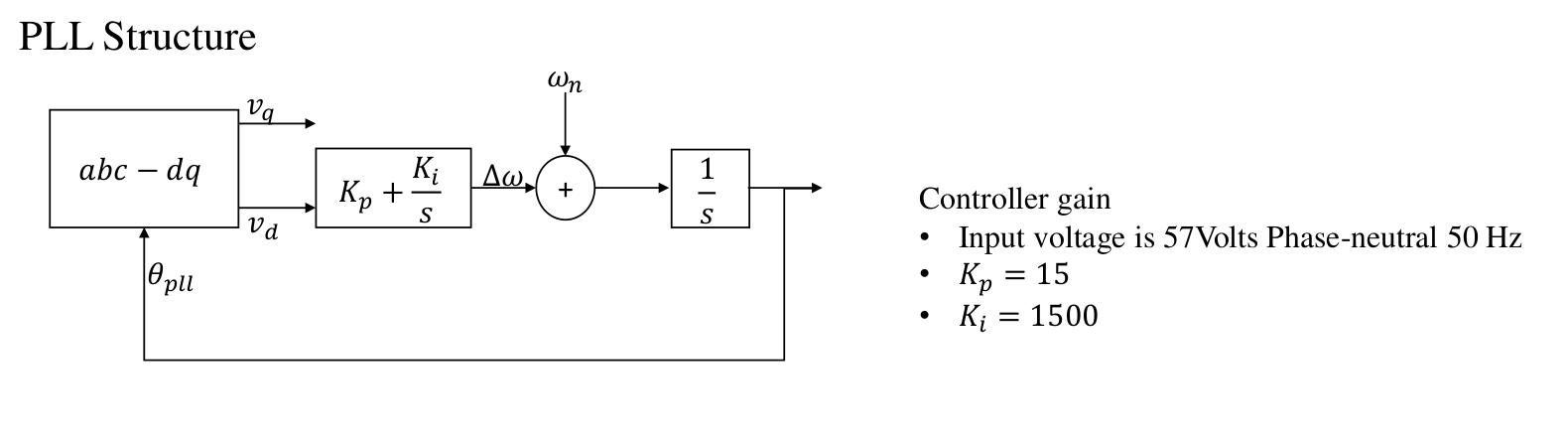
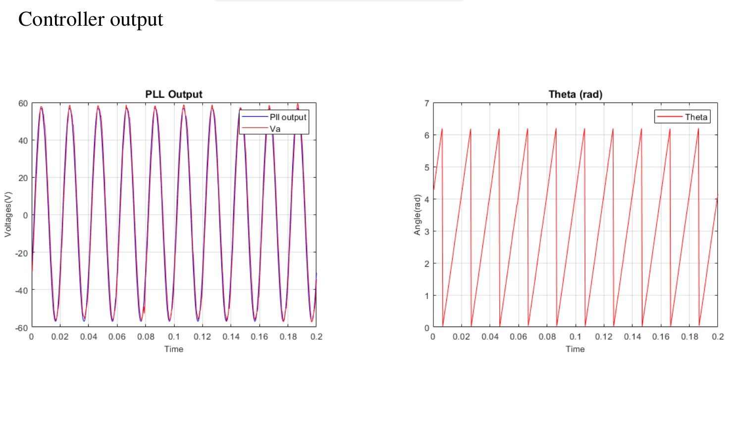
• PLL: estimating phase angle and frequency of input supply
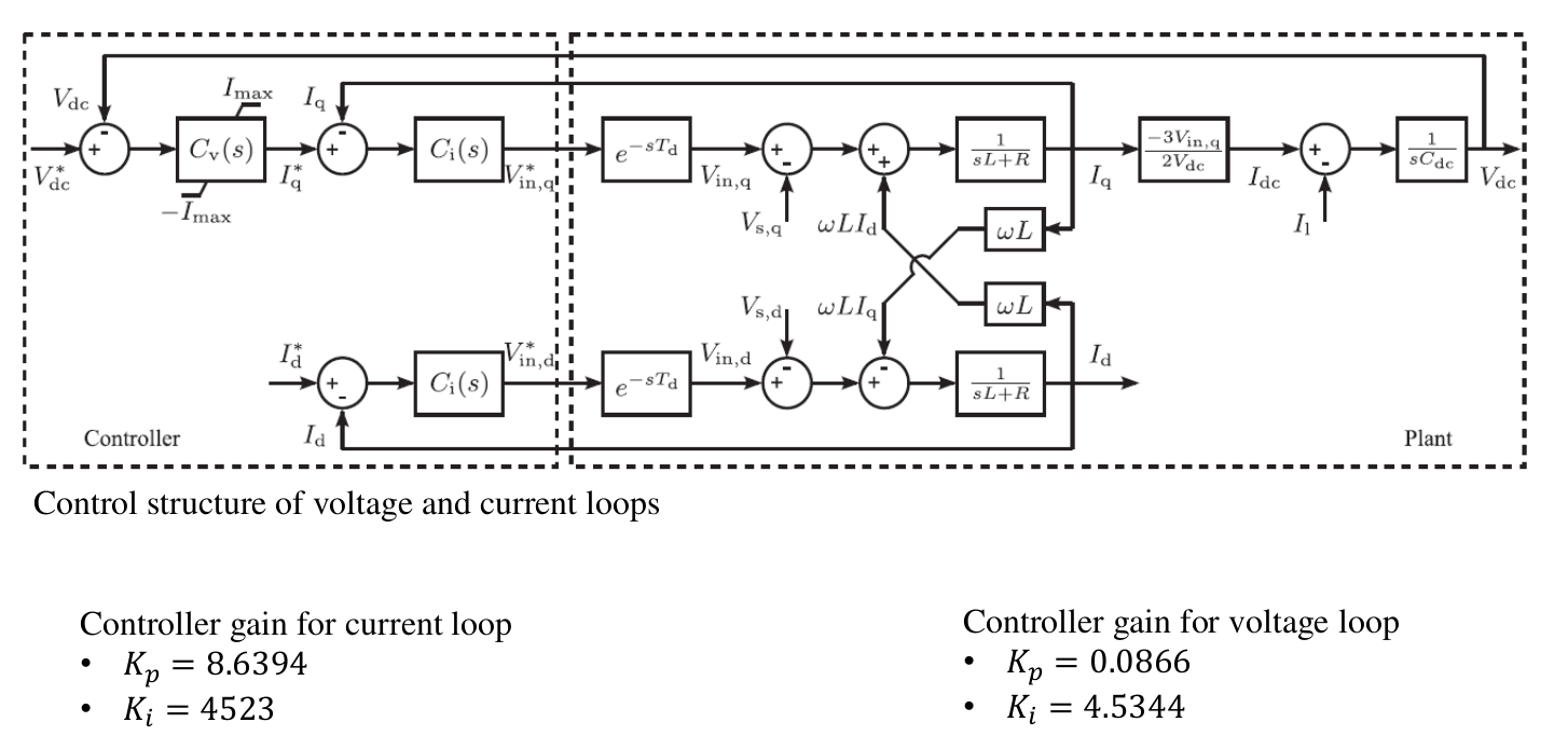
• Voltage Control Loop: It generates the required Iq current.
• Current Control Loop: It generates the required modulation signals.
These modulation references are converted into three sinusoid modulation signals which
are loaded to PWM_CMPA register.
In the while loop controller is waiting for inputs(pwm_en, relay_en) from user.
The PWM and relay contact will not start without these inputs.
Protection Features
• Overvoltage Protection: The controller is continuously scanning all the voltage. In case of voltage goes beyond the VDC_MAX_LIMIT. Controller disable all the
relays.
• The PDA card also have a protection feature, it gives fault signal when there is any problem on the rectifier board for e.g. PWM signals not having deadband. The
controller has a logic, if the fault signal is low than controller will not allow pwm_en and relay_en signals.
• When relay_en is low pwm_en cannot go high, even if the user try to make it high.
Startup Sequence
• First turn on all the power supplies.
• PDA card will show green led means there is no fault.
• Turn on relays by making relay_en high. Relay will make contact.
• Slowly increase the power supply till the required voltage is achieved.
• Turn on the pwm_en signal.
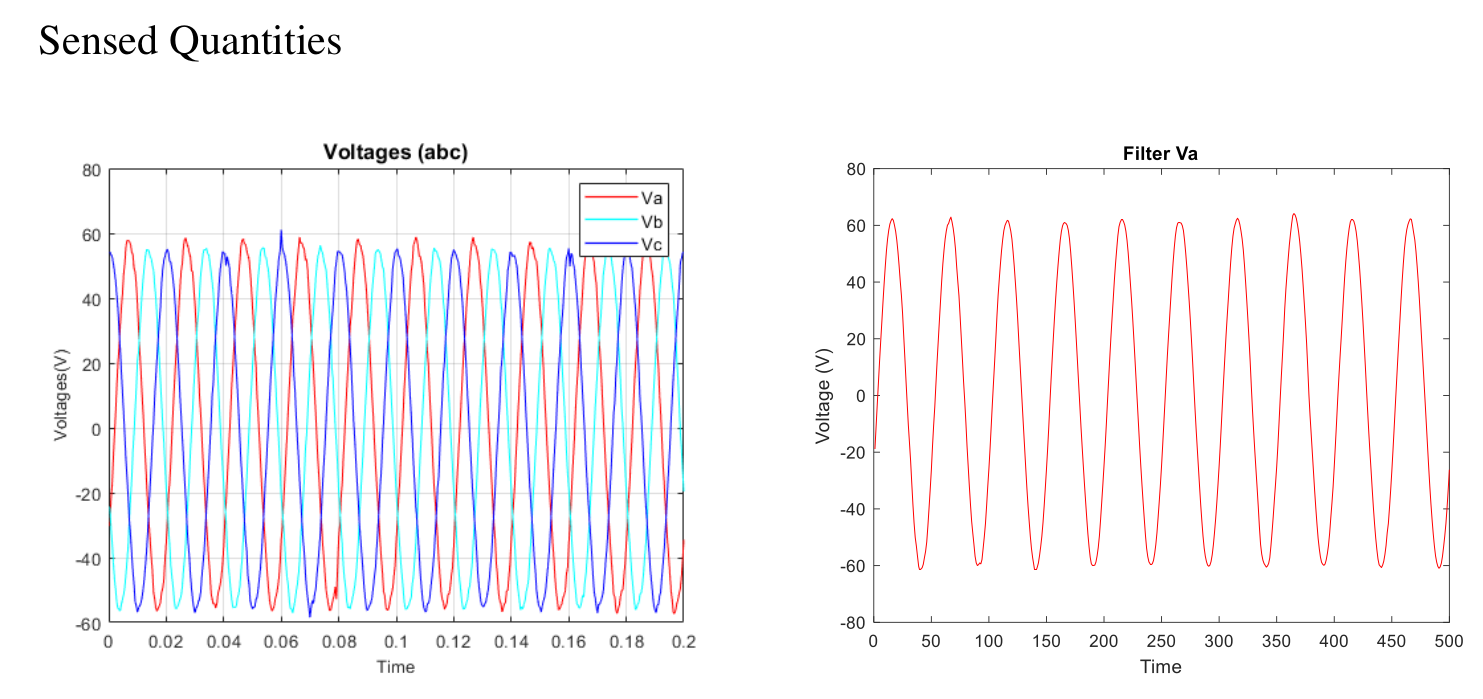
It shows the performance of Butterworth filter on the input ADC data as shown by Va parameter.


Code: RecitiferController_Project_finalVer
MatlabCode_3phaseRectifier_Controller
Recent Comments